Route a 3D sketch path between 2 points
You can use the Routing Path command to route an orthogonal 3D sketch path between keypoints in part or sheet metal, or in a 3D sketch in an assembly.
-
In a part or sheet metal document, select the 3D Sketching tab→3D Draw group→Routing Path command
 .
.In an assembly document, the command is located on the Home tab.
-
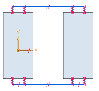
Click the start point for the path.
-
Click the end point for the path.
-
On the command bar, do one of the following:

-
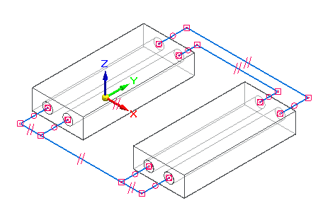
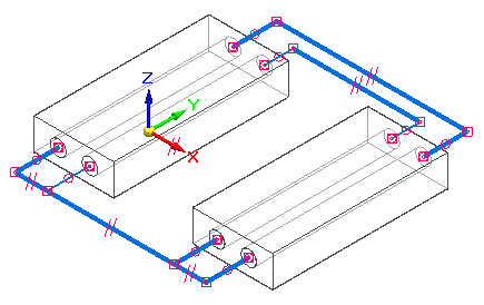
If an alternative path is available for the selected keypoints, you can click the Previous and Next buttons to view the path options. The order of the paths goes from the simplest path, with the least number of segments, to the most complex path.
-
If there is only one path available, or if you want to use the displayed path, click Accept.
-
You can use other options on the command bar to:
-
Define a specific length for the segments that extend from the selected keypoints in the Port segment length box.
-
To route the 3D sketch path relative to a user-defined coordinate system instead of the Base coordinate system, you can select it from the Coordinate System list.
-
Choose a different color, line style, or line thickness to the path.
© 2021 UDS