Activity: Work with sketch regions
Activity: Work with sketch regions
This activity guides you through the process of drawing a sketch to observe when regions are formed. You will also learn how to select regions.
Open a part file
-
Start QY CAD.
-
On the Application menu, click→New→ISO Metric Part.
Draw a rectangle
-
On the Sketching tab→Draw group, choose the Line command
 .
. -
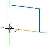
Draw a rectangle. Notice that as soon as the last line connects to the first line, a region forms. (1) denotes the first point.


Select the region
-
On the Home tab→Select group, choose the Select command
 .
. -
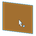
Move the cursor over the rectangle and notice the color change. Closed sketches (regions) and faces highlight as the cursor moves over them.

-
Select the region and notice the color change. The region can be used to create an extrusion or a revolved extrusion. Press the Esc key to end the Select command.

Create nested regions
-
On the Sketching tab→Draw group, choose the Rectangle command
 .
. -
Draw another rectangle that overlaps the first rectangle as shown.

Select multiple regions
-
Move the cursor over the overlapping rectangles and notice the regions formed.

-
Select each region and notice that the previously selected region is deselected.

-
To select multiple regions, select a region and then press the Spacebar.
Note:The Spacebar sets the select mode to add/remove
 . If you select an element that is already selected, it is deselected. If you select an element not already selected, it is selected.
 -
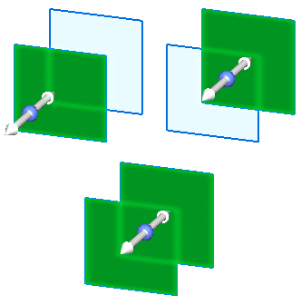
Create the following select sets. Press Esc after each select set is created.

The two overlapping rectangles forms three regions.
Summary
In this activity you learned how to create and select regions. Creating a synchronous feature in QY CAD requires a region.
© 2021 UDS