Activity: Creating a Feature Library
Feature Library Overview
![]()
The feature library enables you to store and reuse part and sheet metal features. If you frequently model the same feature in many part or sheet metal files, you can save a great deal of time by storing the feature in a feature library one time, and then dragging that feature from the feature library to each new part that requires it.
The example shown in this tutorial is a set of shapes that correspond to individual custom punches and sets of related features that are frequently modeled as groups.
In addition to storing a single feature in the feature library, you can store several related features as a unit. There are limitations to this capability, which you can read more about in the QY CAD Help topics.
Launch the Activity: Creating a Feature Library.
Display the Feature Library page
-
Open the sheet metal document ...\Program Files\UDS\QY CAD 2022\Training\sesscfl.psm.
-
Click the Application button
 .
. -
On the Application menu, choose the Save As→Save As command
 .
. -
On the Save As dialog box, save the part file to a new name or location so other users can complete this activity.
-
On the left side of the graphic window, click the Feature Library tab
 .
.
Create a Feature Library folder
-
On the Feature Library page, click the arrow on the Look In control, then browse to the location where you want the new folder to reside.
-
On the Feature Library page, click the Create New Folder button
 .
. -
On the Create New Folder dialog box, type: Feature Library, and then click OK. You can use a different folder name if that is more convenient for you.
The feature library name you type should display as the current feature library folder.

If you did not create a folder for the files you will use in this tutorial, you will do so now.
Set the Feature Library folder Preview option
-
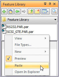
Position the cursor within the file list section of the Feature Library page, then right-click to display the shortcut menu.
-
On the shortcut menu, if a checkmark is not displayed adjacent to the Preview option, click Preview to display the preview area.
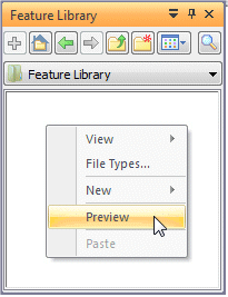 Note:
Note:Because the active feature library folder is empty, the preview area is empty.
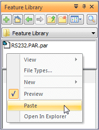
Copy a feature from Feature PathFinder to the clipboard
-
In PathFinder, position the cursor over Cutout 1, then right-click to display the shortcut menu.
-
On the shortcut menu, click Copy.
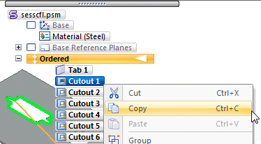
In the next few steps, you will copy a feature of the model to the clipboard, then paste the feature into the feature library. Each set of features you add to the Feature Library is stored as an individual feature library member file.
Later you will learn how to drag library members from the feature library to a part or sheet metal document.
Paste the feature into the Feature Library
-
Click the Feature Library tab
. -
Position the cursor over the list area at the top of the Feature Library page, then right-click to display the shortcut menu.
-
On the shortcut menu, click Paste to paste the feature into the active feature library folder.
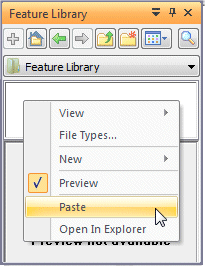
When you click Paste, the Feature Set Information dialog box is displayed. This will be explained in the following steps.
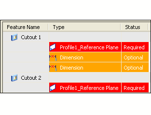
Observe the Feature Set Information dialog box
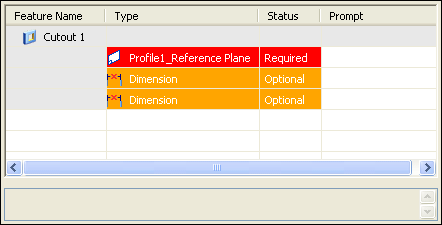
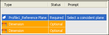
When you paste a feature into the Feature Library page, you can use the Feature Set Information dialog box to review the feature elements which were captured, review their status, and to define custom prompts and notes for when you place the library member later.
Defining prompts and notes makes it easier for other users to use feature library members.
Take a few moments to observe the rows and columns on the dialog box.
You can resize the dialog box to make it easier to see all the columns at one time.
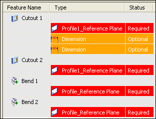
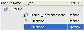
Notice that there are three elements indented under the Cutout 1 row: a profile plane and two dimensions. Also notice the Status column.
When you place the library member later, you must define a planar face or reference plane because its status is listed as Required.
The two dimensions have a status of Optional. When you place the library member later, you can define new edges for the dimensions or you can skip them, and define the edges later.
You will use both approaches later in this tutorial.
Define a custom prompt for the profile plane entry
-
In the Prompt column, double-click the cell for the profile plane row, then type the following:
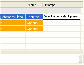
Select a coincident plane
Then press Enter.
-
Click Close to dismiss the dialog box.
This will be the custom prompt for this step when you place the library member.
For this feature, this is all that is required.
When you click Close, a Library entry name dialog appears. Continue with the next page.
Name the feature library member
-
In the Library entry name field, type RS232.PAR as the new member file name.
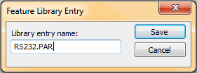
-
Click Save. The member entry is added to the Feature Library page.
Create a feature library member that contains multiple features
-
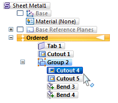
In PathFinder, select Cutout 4. Then hold the Ctrl key, position the cursor over Cutout 5, and click.
-
With both features selected, right-click to display the shortcut menu, then click Copy.
Next, you will copy several features as a set from PathFinder to the Feature Library, thereby creating a single Feature Library member that contains more than one feature.
Paste the features into the Feature Library
-
Display the Feature Library page, right-click to display the shortcut menu, then click Paste.
The Feature Set Information dialog box is displayed.
In the next few steps, you will look at this more closely.
Observe the Feature Set Information dialog box
Notice that for this library member, two features are listed.
The first feature has a profile plane listed as a required element, and two dimensions as optional elements.
The second feature lists only a profile plane as a required element.
When you place this library member, you will need to define two profile planes; one for each feature.
You can also define new edges for the dimensions, or skip the dimensions, and reattach them later.
When creating library members with multiple features, the first feature in the set can have positional dimensions to external edges, because this helps you accurately position the library member on the model.
Ideally, the remaining features in the set should have no dimensions or geometric relationships to any feature outside the set of features that make up the library member.
The features in this set are associated with one another by dimensional and geometric relationships, but only the first feature has external dimensional dependencies.
Define a custom prompt and notes for the library member
-
Double-click the Prompt cell for the first profile plane row, then type the following:
-
Select a coincident plane
-
Press Enter.
-
-
With the first profile plane row still selected, click the Notes box at the bottom of the dialog box, then type:
Use the same X-axis orientation for both profile planes
For this library member, this is all that is required.
-
Click Close to dismiss the dialog box.
When you click Close, a Library entry name dialog appears. Continue with the next page.

For this library member, you want the profile plane X-axis for both features to match when placing the feature. You can use a note to remind users of this requirement.
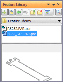
Name the new Feature Library member
-
In the Library entry name field, type SCSI_GTE.PAR as the new member file name.
-
Select Save. The member entry is added to the Feature Library page.
Create another Feature Library member that contains multiple features
-
In PathFinder, select Cutout 6, Cutout 7, Bend 1, and Bend 2.
-
With the features selected, right-click to display the shortcut menu, and then click Copy.
As discussed earlier, when creating library members with multiple features, the first feature in the set can have positional dimensions to external edges, but the remaining features should have no dependencies to any other feature outside the set.
The features in this set are associated with one another by dimensional and geometric relationships, but none of the features has any dependencies on any other feature outside the set.
Paste the features into the Feature Library
-
Display the Feature Library page, right-click to display the shortcut menu, then click Paste.
The Feature Set Information dialog box is displayed.
In the next few steps, you will look at this more closely.
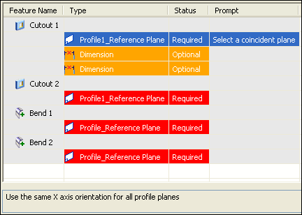
Observe the Feature Set Information dialog box
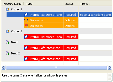
Notice that for this library member, four features are listed.
The first feature has a profile plane listed as a required element, and two dimensions as optional elements.
The remaining features each list only a profile plane as a required element.
When you place this library member, you will need to define four profile planes; one for each feature.
You can also define edges for the dimensions, or skip the dimensions, and reattach them later.
Define a custom prompt and notes for the library member
-
Double-click the Prompt cell for the first profile plane row, then type the following:
-
Select a coincident plane
-
Press Enter.
-
-
With the first profile plane row still selected, click the Notes box at the bottom of the dialog box, then type:
Use the same X-axis orientation for all profile planes
For this library member, this is all that is required.
-
Click Close to dismiss the dialog box.
When you click Close, a Library entry name dialog appears. Continue with the next page.
For this library member, you want the profile plane X axis for all features to match the first feature when placing the member. You can use a note to remind users of this requirement.
Name the new Feature Library member
-
In the Library entry name field, type RJPORT.PSM as the new member file name.
-
Select Save. The member entry is added to the Feature Library page.
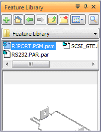
Notice that for this library member, QY CAD assigns a PSM extension to the member file name, but the members you created earlier have PAR extensions.
This first two library members contained only cutouts, which are valid in both part and sheet metal documents.
The third library member contains features which are valid only in sheet metal documents. The Feature Library functionality manages this for you automatically.
In the next few steps, you will close this document, create a new sheet metal document and base feature, then place library members in the new document.
Create a new sheet metal document
-
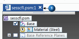
Close sesscfl.psm by clicking the X (1) above the graphic window.
-
Click No in response to the Do you want to save changes to the following document?.
-
Choose Application menu→New→New.
-
From the Standard Templates list, choose ISO Metric, and then choose iso metric sheet metal.psm.
-
Click OK to create the new document.
Transition to Ordered environment
-
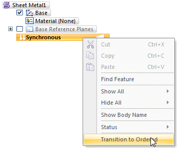
In PathFinder, place your cursor over Synchronous.
-
Right-click and in the shortcut menu select Transition to Ordered. PathFinder will reflect this.
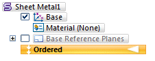
If your user profile is set to start part and sheet metal documents in the Ordered environment, you can skip onto the next page. You can check this by choosing Application menu→Settings→Options→Helpers→Starting QY CAD and confirming you have Ordered selected under Start Part and Sheet Metal documents using this environment:.
The following steps describe how to change from synchronous to ordered.
Construct a 100 mm by 100 mm tab
-
Choose the Home→Sheet Metal→Tab command
 .
. -
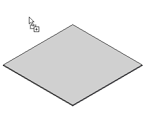
Construct a 100 mm by 100 mm tab on the top reference plane, as shown.
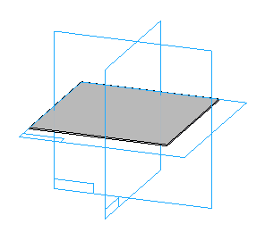 Note:
Note:Ensure that you turn on Base Reference Planes in PathFinder.
If you are comfortable constructing the feature on your own, you can skip the step-by-step instructions.
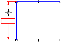
Select the top reference plane
-
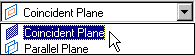
On the Tab command bar, in the Create-From Options list, click the Coincident Plane option.
-
Position the cursor over the top reference plane, as shown. When the plane highlights, click.
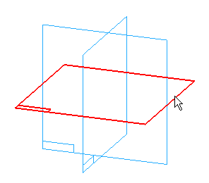
Draw a rectangle
-
Choose the Home→Draw→Rectangle by 2 Points command
 .
. -
Position the cursor approximately where the top left end of the line is shown, and then drag down to the bottom right end.
The ends of this line represent two diagonal corners of the rectangle. The system constructs a rectangle with vertical sides and a horizontal top and bottom.
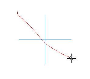
Dimension the sides of the rectangle
-
Choose the Home→Dimension→Smart Dimension command
 .
. -
Click the left side of the rectangle, position the vertical dimension as shown, and then click again to place it.
-
Type 100 mm in the dimension value box. Press Enter.
-
Dimension the bottom of the rectangle in the same way, also defining a value of 100 mm.
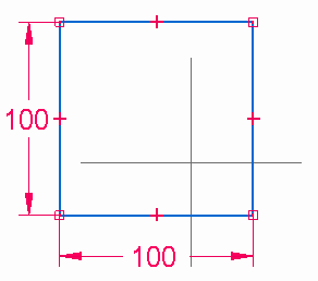
Finish the profile
-
The dimensions on your profile should now match the illustration.
Choose the Home→Close→ Close Sketch command
 .Tip:
.Tip:You can also close the sketch using the Close Sketch icon in the top-left corner of the graphics window
 .
.
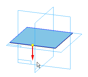
Specify the extent of the tab
-
Position the cursor below the top reference plane, as shown, and click to extend the material below the profile.
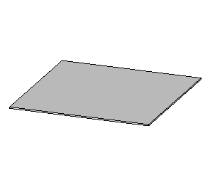
Finish the feature
-
On the Tab command bar, click
 to complete the feature.
Hide the default reference planes and reorient the view
-
Choose the Home→Select→Select command
 .
.In the graphics window, position the cursor away from any geometry, then right-click to display the shortcut menu.
-
On the shortcut menu, point to Hide All, then click Reference Planes.
The reference planes are hidden in the graphic window.
-
On the keyboard, hold the Ctrl key down, then press the I key to rotate the view to the isometric orientation.
Drag a feature from the Feature Library
-
Click the Feature Library tab
. -
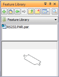
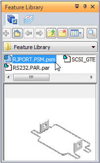
Set the Feature Library folder to the folder where you created the library member files earlier.
-
Position the cursor over the RS232.PAR library member file you created earlier, and drag the member into the graphic window.
-
Release the mouse button and the Feature Set Information dialog box is displayed.
Reposition the Feature Set Information dialog box
-
Drag the Feature Set Information dialog box to a position where you can see both the command bar and the graphics window.
Notice that the first row in the Feature Set Information dialog box is active, which requires that you define a profile plane.
Also notice that the prompt you defined earlier is displayed in the Prompt Bar.
Define the profile plane
-
On the command bar, in the Create-From Options list, ensure the Coincident Plane option is set.
-
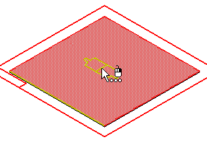
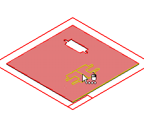
Position the cursor over the top face, as shown, but do not click to place it.
You can control how features are placed on the part by defining the X-axis orientation of the reference plane.
-
Press the N key on the keyboard until your display matches the illustration, then click to define the profile plane.
When you place a feature from the Feature Library, you must select the profile plane upon which the feature will be placed. You can use any of the reference plane definition options on the command bar.
This step is exactly as it would be if you were constructing the feature from scratch.
For this feature, you want to use the top face of the tab as the profile plane of the feature.
Select the edge for the first dimension
![]()
Notice that the graphic window display has updated, and that a 25 millimeter dimension is displayed in the Highlight color.
Also notice that the Feature Set Information dialog box has updated. The status for the profile plane is now listed as Defined, and the row colors indicate that the next step is to define the first dimension.
-
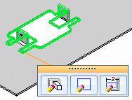
In the graphics window, select the edge shown in the top illustration.
Select the edge for the second dimension
![]()
Notice that the graphics window display has updated again. The 25 millimeter dimension has been placed, and a 30 millimeter dimension is displayed in the Highlight color.
Also notice that the Feature Set Information dialog box has updated. The status for the first dimension is now listed as Defined, and the row colors indicate that the next step is to define the second dimension.
-
In the graphics window, select the edge shown in the top illustration.
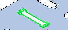
Finish the feature placement
Notice that a cutout feature, identical to the one you copied to the Feature Library at the beginning of this tutorial, has been placed on the tab.
Also notice that on the command bar, the Repeat button is active. This allows you to place another instance of the library member.
-
On the Feature Set Information dialog box, click Close.
Display the Feature PathFinder page
-
Choose the Home→Select→Select command
. -
Display PathFinder.
Notice that a single new feature, Cutout 1, has been added to the feature tree. The feature you placed from the Feature Library now behaves as if you had drawn it from scratch.
Place the RJPORT.PSM member from the Feature Library
-
Click the Feature Library tab
. -
Position the cursor over the RJPORT.PSM library member file you created earlier, and drag the member into the graphics window.
-
Release the mouse button and the Feature Set Information dialog box is displayed.
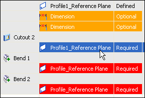
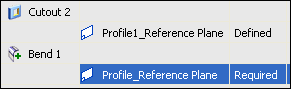
Observe the Feature Set Information dialog box
If necessary, drag the Feature Set Information dialog box to a position where you can see both the command bar and the graphic window.
Notice that for this member, four profile planes are required. For this member, you will skip the dimensions, and attach them later.
Also notice the Note box, which reminds you that the X-axis orientation for all profile planes should be the same.
Define the first profile plane
-
Position the cursor over the top face, as shown.
-
If your X-axis orientation for the profile plane does not match the illustration, press the N key on the keyboard until your display matches the illustration, then click to define the profile plane.
For this feature, you again want to use the top face of the tab as the profile plane of the feature.
Skip the dimensions
To skip dimensions when placing a feature library member, you select the next profile plane entry in the Feature Set Information dialog box.
Skipping dimensions is useful when the original dimensions for the library member are not appropriate for the current model. You will learn more about this later.
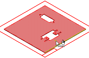
Define the second profile plane
-
Position the cursor over the top face, as shown. It does not matter where the profile elements are positioned on the face, only that the correct face highlights, and that the X-axis orientation matches the first profile plane.
When the original set of features were constructed, the profiles for the second, third, and fourth features were fully constrained to edges that were part of the feature set.
This ensures that the profile will be positioned correctly on the face.
-
If your X-axis orientation for the profile plane does not match the illustration, press the N key on the keyboard until your display matches the illustration, then click to define the profile plane.
Notice that the Feature Set Information dialog box updates to show that the profile plane for the cutout is now listed as Defined.
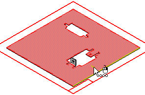
Define the third profile plane
-
Position the cursor over the top face, as shown. Again, it does not matter where the profile elements are positioned on the face, only that the correct face highlights, and that the X-axis orientation matches the first profile plane.

-
If your X-axis orientation for the profile plane does not match the illustration, press the N key on the keyboard until your display matches the illustration, then click to define the profile plane.
Notice that the Feature Set Information dialog box updates to show that the profile plane for the Bend 1 feature is now listed as Defined.
You are now ready to define the profile plane for the Bend 1 feature.
Define the fourth profile plane
-
Position the cursor over the top face, as shown.

-
If your X-axis orientation for the profile plane does not match the illustration, press the N key on the keyboard until your display matches the illustration, then click to define the profile plane.
Notice that the Feature Set Information dialog box updates to show that the profile plane for the Bend 1 feature is now listed as Defined.
You are now ready to define the profile plane for the Bend 2 feature.
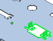
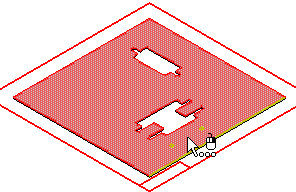
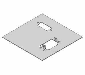
Observe the result and finish the placement
-
On the Feature Set Information dialog box, click Close.
-
Choose the Home→Select→Select command
.
![]()
Your display should match the illustration.
Notice that a set of features, identical to the features you copied to the Feature Library at the beginning of this tutorial, have been placed on the tab.
The orientation for these features is different than the original, because the profile plane orientation was different.
Also notice that on the command bar, the Repeat button is active.
Observe PathFinder
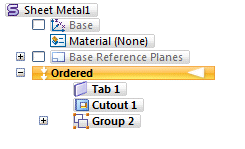
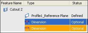
Notice that a group was added to PathFinder.
When placing a feature library member that is set of features, a group is created and the set of features are collected in the group.
-
Click the plus symbol (+) to expand the group.
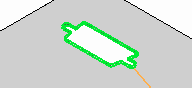
Observe the feature group and select the cutout feature
Notice that two cutout and two bend features are within the feature group.
-
Select the cutout feature as shown in the illustration.
Notice that it also highlights in the graphic window.
In the next few steps, you will edit the cutout feature and attach the dimensions you skipped.
Set the Dynamic Edit option and display the profile elements
-
On the Select edit handle, click the Dynamic Edit button
 .
.The profile, profile plane, and dimensions for the cutout are displayed.
-
Choose the Fit command
 to fit the contents of the view to the graphics window.
Your display should now be similar to the top illustration. Your dimensions may have different values than the illustration.
![]()
To attach the dimensions, you must edit the profile for the selected cutout.
The edit handle should be displayed as shown below.
Reattach the first dimension
![]()
![]()
![]()
To reattach the first dimension, do the following:
-
(1) Select the dimension.
-
(2) Position the cursor over the end of the dimension you want to attach. The cursor changes shape.
-
(3) Drag the cursor over the edge you want to attach the dimension to.
The dimension value changes to the actual distance between the edge and the profile element.
Reattach the second dimension
![]()
![]()
![]()
To reattach the second dimension, do the following:
-
(1) Select the dimension.
-
(2) Position the cursor over the end of the dimension you want to attach. The cursor changes shape.
-
(3) Drag the cursor over the edge you want to attach the dimension to.
The dimension value changes to the actual distance between the edge and the profile element.
Finish editing the feature
-
Click twice slowly in empty space to finish editing the feature.
-
Click the Fit button to fit the contents of the view to the graphics window
.
Save the file
![]()
-
On the Quick Access toolbar, click the Save button to save the work you have done so far
 .
.
© 2021 UDS