Modify FEA symbol properties
Modify symbol size and spacing
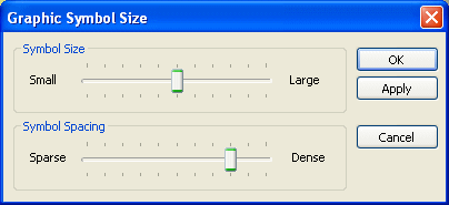
You can change the size and spacing of the load, constraint, and assembly connector symbols using the Graphic Symbol Size dialog box.
-
Select a load, constraint, or assembly connector in the Simulation pane, or click a symbol you want to modify in the graphics window.
-
Click its edit definition handle in the graphics window.
Note:The edit definition handle looks like a 3D annotation, for example, Force 1, Pressure 1, Fixed 1, Glued 1.
-
On the command bar, click the Graphic Symbol Size button
 .
. -
In the Graphic Symbol Size dialog box, do any of the following:
-
Adjust the size of the symbols by moving the Graphics Symbol Size slider.
-
Adjust the density of the symbols by moving the Graphics Symbol Spacing slider.

-
Modify symbol color
You can change the color for the symbols and the value label associated with a selected load, constraint, or connector symbol.
-
Select a load, constraint, or assembly connector in the Simulation pane, or click a symbol you want to modify in the graphics window.
-
Click its edit definition handle in the graphics window.
Note:The edit definition handle looks like a 3D annotation, for example, Force 1, Pressure 1, Fixed 1, Glued 1.
-
On the command bar, click the Color button
 .
. -
In the Color dialog box, make changes to the existing color or define a custom color.
The Color button on the command bar updates to show the current color when you close the dialog box.
Example:
To see what the current color definition is for the different symbols, see these Help topics:
© 2021 UDS