Mesh Options dialog box
The Mesh Options dialog box contains options for improving the mesh results using the Mesh command or the mesh sizing commands. Selected options are applied and saved with the study when you select the Mesh button or the Mesh & Solve button in the Mesh dialog box.
Mesh Sizing options
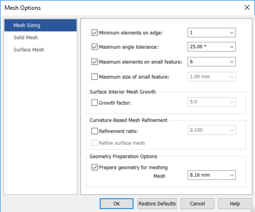
- Minimum elements on edge
-
Specifies the minimum number of elements along any edge on the selected surfaces.
The default value is 1, and the number of elements are determined by the element size. Use this option to set higher numbers if you want to force some degree of refinement.
- Maximum angle tolerance
-
Specifies the maximum allowable angle between the tangent of a surface boundary curve at the start of the element edge, and the angle of the free edge of the element (1).
- Maximum elements on small feature
-
Limits the number of elements placed around the perimeter of an interior boundary, usually around small features, to the value you enter in the Maximum elements on small features box. This prevents a large concentration of elements along small features that may not be needed and can skew the results for your model.
When this option is set, you can enter a value from 3 to 100,000.
- Maximum size of small feature
-
Overrides the element size and directly specifies the size of a small feature. This value is the effective diameter of the interior feature calculated by taking the perimeter length of the interior feature divided by Pi.
- Surface Interior Mesh Growth
-
- Growth factor
-
Target size of all of the elements in the interior of the surface. It is multiplied by the average size of the elements around the perimeter of the surface.
Growth factor affects mesh quality.
Example:If you want to decrease the size of the elements in the interior of the surface, use a number between 0 and 1; to increase the size, use a value above 1.
Using a value of 5.0, the most stringent value, may cause meshing problems in complex geometry.
- Curvature-Based Mesh Refinement
-
The Curvature-Based Mesh Refinement options work together to reduce the size of elements in areas of a surface with a high amount of curvature.
In this process, the surface is meshed first at the initial element size. Then the ratio of Chord Height to Chord Length is calculated for each element. If this ratio is larger than the value specified, the element size is automatically reduced and the surface is meshed again with the new sizing. This continues until all the elements on that surface do not exceed the Refinement ratio.
- Refinement ratio
-
Refinement Ratio≡Chord Height÷Chord Length
Where Chord Height (1) is the maximum normal distance from the element edge to the curve or surface, and Chord Length (2) is the length of the element edge.
- Refine surface mesh
-
Refines the surface mesh using the Refinement ratio.
- Geometry Preparation Options
-
Use the following options to eliminate unnecessary geometry features, such as small surfaces and short edges. This is based on the global mesh size and active geometries, so that the meshing process is more robust and generates better quality elements.
- Prepare geometry for meshing
-
When a model contains very small faces or edges that can cause meshing to fail, specifies that an advanced algorithm is applied to simplify the geometry so that mesh processing completes.
This option is on by default.
- Mesh
-
Specifies a user-defined value so that the geometry that is required for meshing is extracted, and the small facets and slivers below this value are ignored. You can try different values and remesh the model to achieve a successful mesh.
Example:Before—Sliver geometry is visible.
After—Geometry is simplified.
 Note:
Note:You also can use the Geometry Inspector to aid in cleaning up complex geometry. For more information, see Removing geometry flaws and small entities.
Solid Mesh options
- Midside nodes on surfaces
-
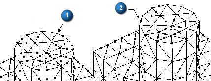
Creates midside nodes in the tetrahedral mesh to provide a higher degree of accuracy. On individual faces of the tetrahedral element, this option creates parabolic surface elements instead of linear surface elements.
In this example, midside nodes were projected onto the surfaces and edge curves. Notice the accurate representation of the cylindrical portion of this model, since the midside nodes are actually on the radius of the cylinder. (1) Without midside node projection, the cylindrical portion is more faceted. (2)
- Limit midside distortion angle
-
Limits the distortion of parabolic elements created by the Midside nodes on surfaces option.
- Maximum angle
-
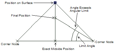
Specifies the maximum angle of distortion of the parabolic elements.
If the limit distortion option is on, you must specify an angular limit to the distortion. Femap will calculate the position of the midside node on the surface, and then compare the resulting angles with the two corner nodes. If either of these angles is above the specified limit, Femap will recompute a new position for the node on the line between the exact midside position and the position on the surface, which creates an angle equal to the limit angle.
Surface Mesh options
- Allow mapped meshing
-
When checked, creates a mapped mesh with regular, structured elements. A mapped mesh uses the values set for Maximum angle tolerance and Minimum elements on edge to determine corners it can use to create surface elements.
When unchecked, the selected surface or surfaces mesh with a free mesh, which consists of elements with random, irregular shapes.
- Other Meshing Options
-
- Post-meshing cleanup
-
Checked by default, attempts to eliminate specific patterns in a mesh in an effort to create an overall higher quality mesh. It also does additional element checking in an attempt to eliminate meshing situations which may cause problems with surface and solid meshing.
Note:In almost all cases, the Post-meshing cleanup option should be selected, as it usually creates a better overall mesh. The only potential drawback to using this option is the possibility that the cleanup will replace patterns with fewer elements, and therefore create a slightly coarser mesh than expected.
Additional cleanup includes inserting extra mesh points on long cylindrical surfaces with coarse mesh sizing. This eliminates the possibility of elements bridging the gap, resulting in a collapsed hole.
The following example shows mesh patterns and the resulting mesh after using Post-meshing cleanup. In 1, before and after states are presented for patterns; in 2, unwanted diamond-shaped elements are eliminated.
- Maximize quad elements
-
For surface meshes, maximizes the number of quadrilateral elements, and minimizes the number of triangular elements. Quadrilateral mesh elements produce more accurate solutions.
Femap Example
Off
On
- Quad edge layers
-
Specifies the number of layers of quadrilateral elements placed around every boundary curve on a surface. You can choose to have either 1, 2, or 3 layers of quads around each boundary curve of a surface, including internal curves.
 Note:
Note:If you enter a number higher than 3 directly into the box, the mesher attempts to create the specified number of quad element layers. If there is not enough room for the requested number of layers based on the mesh size, as many layers as possible are created.
- Smoothing
-
Adjusts the locations of element corner nodes to reduce distortions in those elements. Smoothing is performed automatically by all free-meshing options described above, but you also can use it to smooth any planar or solid element mesh manually.
- Laplacian
-
Pulls a node toward the center of surrounding nodes directly connected to that node along an element edge.
- Centroidal
-
Pulls a node toward the element-area-weighted centroid of the surrounding elements.
 Note:
Note:The Laplacian method usually produces the mesh with the least element distortion. It is also the faster method. Centroidal smoothing usually produces a mesh that has more uniform element sizes.
- Max iterations
-
For either of the two smoothing methods–Laplacian or Centroidal—specifies the maximum number of iterations used to converge toward a smoother mesh. At the conclusion of each iteration, the smoothing is reevaluated with the updated nodal locations. This process continues until the maximum number of iterations is exceeded, or until no node is moved by a greater distance than the tolerance value entered in the Smooth to box.
- Smooth to
-
Specifies a maximum distance that an individual node can be moved during smoothing iterations.
© 2021 UDS