Activity: Apply a surface mesh to a sheet metal part
-
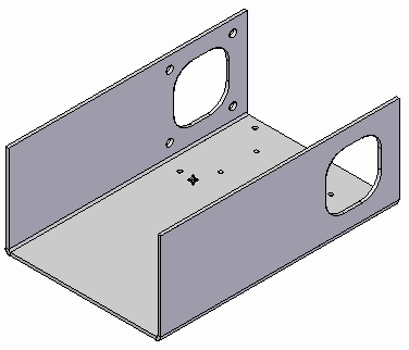
Open the file FE_enclosure.psm.
Simulation models are delivered in the \Program Files\UDS\QY CAD 2022\Training\Simulation folder.
-
Create a study.
All analyses must have an active study. No study exists for this part, so you will create one.
-
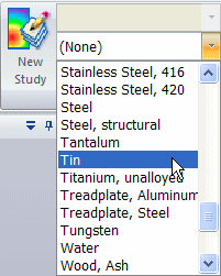
In the Simulation tab→Study group, select Tin from the Material List.
-
Select New Study.
 .
. -
For a sheet metal model, the Mesh Type defaults to Surface. From the Study Type list, choose Linear Static and click OK.
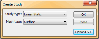
You can see the new study in the Simulation tab→Study group.

-
-
Define a mid-surface.
Analysis of a sheet metal part (or any thin part) requires a mid-surface.
-
Choose Simulation tab→Geometry group→Mid-Surface.

-
On the Mid-Surface command bar, do the following:
-
Click Offset From Side 1.
-
Ensure Offset Ratio is set to 0.500.

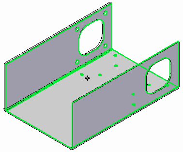
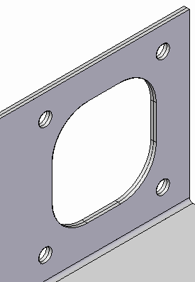
You can see that the part is automatically selected, and the mid-surface is displayed in green
-
Click the Preview button, and then click Finish.
-
Click Cancel to exit the command.
-
Zoom in on the model to see the mid-surface.
-
-
-
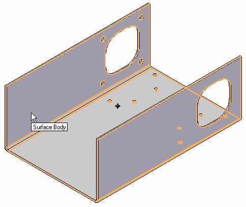
Select the mid-surface.
-
Choose Simulation tab→Geometry group→Define.

-
Select the mid-surface as shown and click Accept.

-
-
Mesh the enclosure.
-
Choose Simulation tab→Mesh group→Mesh.

-
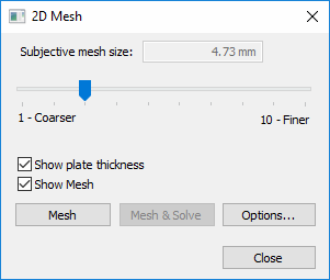
In the 2D Mesh dialog box:
-
Select Show mesh.
-
Click Mesh.
The NX Nastran mesh processing starts and displays a progress meter.
 Note:
Note:In the absence of loads and constraints, you cannot solve the study, but you can mesh the model.
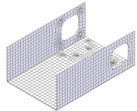
After a short period of time, the enclosure mid-surface displays with a surface mesh.
-
-
-
Change the subjective mesh sizing.
As with tetrahedral meshes, you can change the number of elements using the Subjective mesh slider.
-
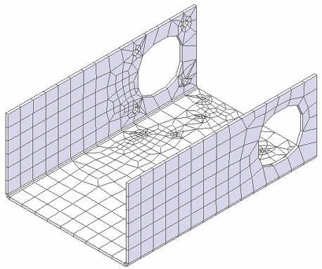
Use the slider to change the mesh size to 1 and click Mesh again.
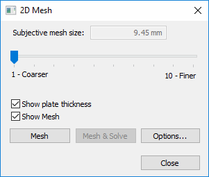
Notice the reduction in the number of elements.
-
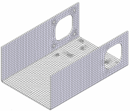
Use the slider to change this to a value of 7, click Mesh again, and review the results.
-
Note that each increase in the number of elements requires an increase in time to mesh the part.
-
An increase in the number of elements results in increased accuracy of the analysis; however, you must decide whether this improvement in accuracy is worth the additional processing time.
-
-
Close this file.
Surface meshes are generally used in the analysis of very thin models; in this activity, you will apply a surface mesh to a sheet metal part.
© 2021 UDS