Tutorial: Simplify a model and apply a load using X, Y, Z components
To get the best results from QY CAD Simulation, you can optimize the geometry in your part, sheet metal, and assembly models. There are several techniques for doing this, such as:
-
Using a simplified model
-
Removing geometry flaws and small entities
-
Offsetting edges around openings, holes, and fasteners
For information about these and other techniques, see Assembly best practices for simulation.
-
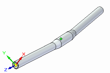
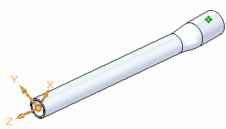
Open the file named FE_bar-XYZ.par. This model represents a bicycle handle bar.
Simulation models are delivered in the \Program Files\UDS\QY CAD 2022\Training\Simulation folder.
-
Simplify the model.
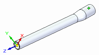
Assume that forces are applied equally by each arm to the bar. By taking advantage of symmetry you speed up processing of the finite element model by cutting the bar in half.
Note:This change affects the design part; for your own production models, it is recommended that you copy a model for this type of simplification.
-
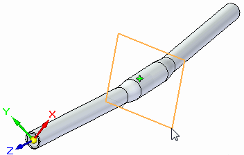
In PathFinder, turn on the Front (xz) base reference plane.
-
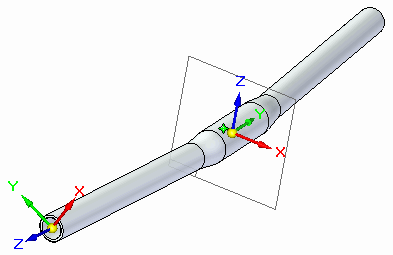
Also in PathFinder, turn on the Base coordinate system.
-
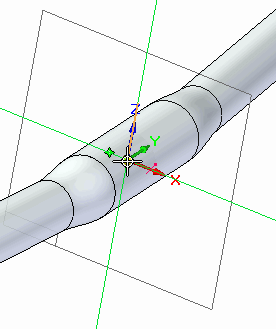
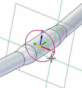
Sketch a circle by center point centered on the origin of the base coordinate system.
-
Define a circle of diameter 75 mm.
-
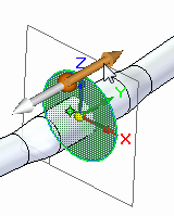
Select the region encompassed by the circle. On the Extrude command bar, from the Add/Cut list, choose Cut
 .
. 
-
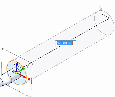
Extrude the circle 375 mm to the right.
-
In PathFinder, turn off the Base coordinate system and the Front (xz) reference plane.
-
-
Create a static study.
-
Select Simulation tab→Study group→New Study.
-
Choose the Linear Static study type and Tetrahedral mesh type. Select OK.
-
-
Add a force.
-
Select Simulation tab→Structural Loads group→Force.
-
On the Loads command bar, from the Direction Type list, select Components
 .
. -
Also on the command bar, from the Select Coordinate System list, select right hand CS
 .
.
-
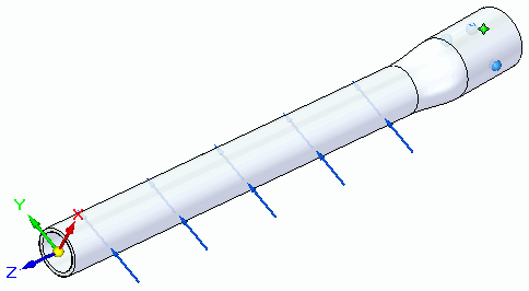
Select the inner and outer cylindrical faces of the bar. In the Fy component box, type and enter a force of 334 N (75 lbf). Set to zero the Fx and Fz components.
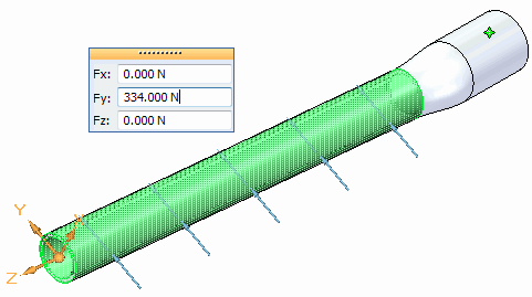
-
Right-click to accept and click to finish.
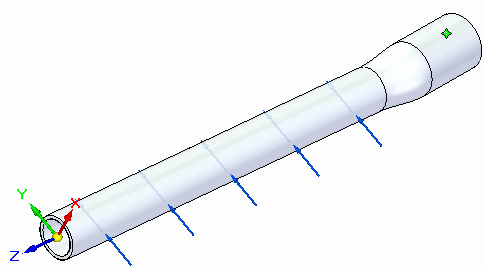
-
-
Define a fixed constraint on several faces.
-
Select Simulation tab→Constraints group→Fixed.
-
Select the inner and outer faces at the right end of the bar.
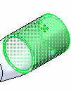
-
Right-click to accept and click to finish.
-
-
Select the Solve command.
After a few moments, the part is meshed and solved.
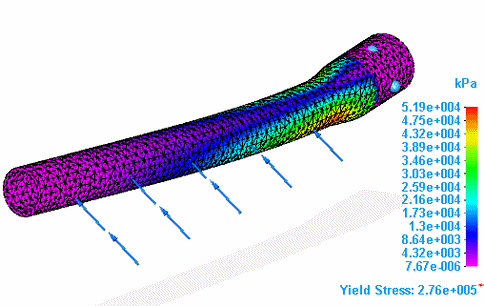
The results are displayed on the deformed model in the Simulation Results environment.
-
Rotate the part to view the area of maximum stress.
-
Close the file.
To speed meshing times in an assembly model, you can use the simplified representation of part and sheet metal geometry in a study. In this tutorial, you learn how to simplify a bicycle handlebar using the Loads command bar→Direction Type list, Component option  .
.
© 2021 UDS