Tutorial: Simulate stresses on a basketball hoop
-
Open FE_Basketball.asm.
Simulation models are delivered in the \Program Files\UDS\QY CAD 2022\Training\Simulation folder.
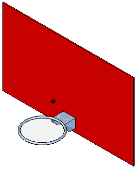
-
Create an analysis study:
-
Select the Simulation tab→Study group→New Study command.

-
Choose the Linear Static study type and Tetrahedral mesh type, and then click OK.
The Define command in the Geometry group is active.

-
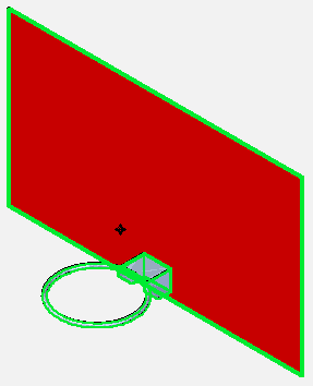
Select the backboard as well as the hoop. Click Accept on the command bar.
-
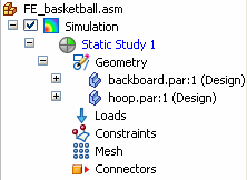
Display the Simulation tab to see the new study. Expand the Geometry node to show the parts you selected.
-
-
Define a force on the rim:
-
Select Simulation tab→Structural Loads group→Force.

-
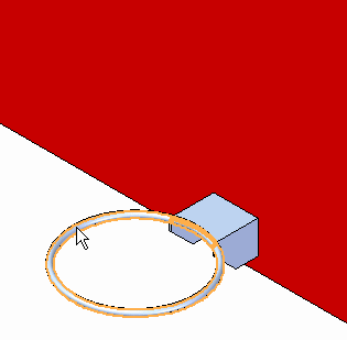
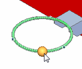
Select the toroidal face comprising the rim.
-
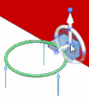
You may need to reorient the load arrow. Select the steering wheel origin.
-
Move the origin to the top face of the hoop support so the major axis points up.
-
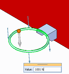
Select the Flip button
 on the Loads command bar to flip the load direction.
 -
Type 1001 N in the value box. This is equal to a 225 pound force load.
-
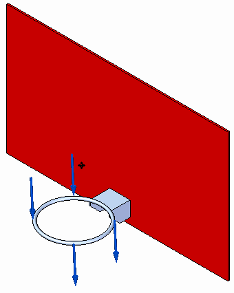
Right-click to accept, and then click to finish.
The force load is placed.
-
-
Add a fixed constraint to the backboard:
-
Rotate the view to see the back side of the backboard.
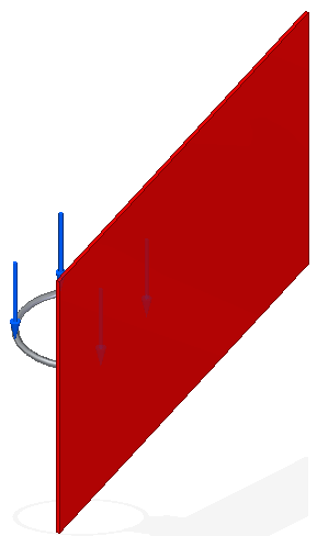
-
Select Simulation tab→Constraints group→Fixed, and select the rear face.
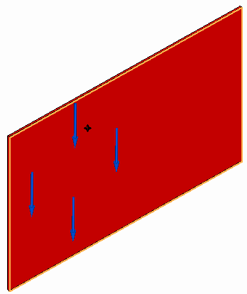
-
Right-click to accept, and then click to finish.
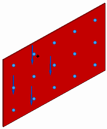
-
-
Define assembly connectors between the rim and the backboard.
Note:For information about assembly connectors, see Glue and no penetration contact connectors.
-
Rotate the model so you can see the rim and front of the backboard.
-
Choose the Simulation tab→Connectors group→Manual command
 .
.The Assembly Connector command bar is displayed.
-
Select the front face of the backboard as the target face.
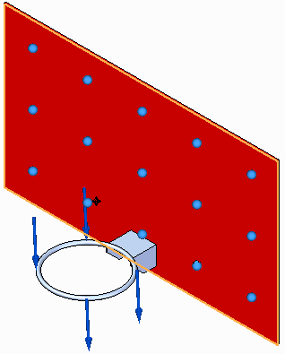
-
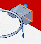
Zoom in around the rim and select the rear face of the rim support as a source face. Use QuickPick if necessary.
Note:Ensure you select the rear face of the support, not the face on the inside of the thin wall portion of the support.
-
Accept the source face selection.
-
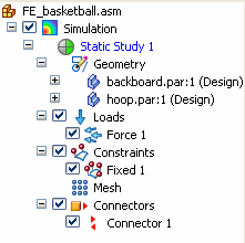
Zoom in around the rim and backboard area to see the connector symbols.
Also notice the Simulation tree-view pane has been updated with the connector.

-
-
Mesh the assembly:
-
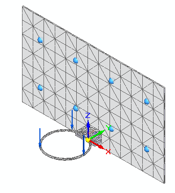
Select the Mesh command, and on the Mesh command bar, use the slider to define a subjective mesh size of 3.
-
Click the Mesh button.
The entire assembly is meshed.
-
-
Solve the study:
-
Select the Simulation tab→Solve group→Solve command.
Note:If a fatal Nastran error message is displayed instead of a solution, change this setting in the Mesh Options dialog box, and then click Solve again:
-
Reopen the Mesh dialog box and click the Options button.
-
On the Mesh Sizing page, in the Geometry Preparation Options section, clear the check box, Prepare geometry for meshing.
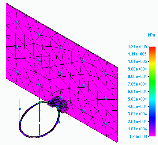
After a few moments, the results are displayed in the Simulation Results environment.
-
-
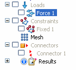
Turn off the display of loads, constraints, and connectors in the Simulation pane.
-
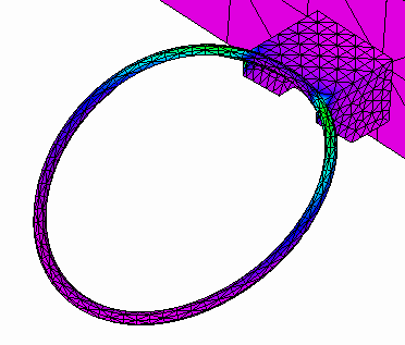
Zoom in on the rim to view the high-stress area.
-
-
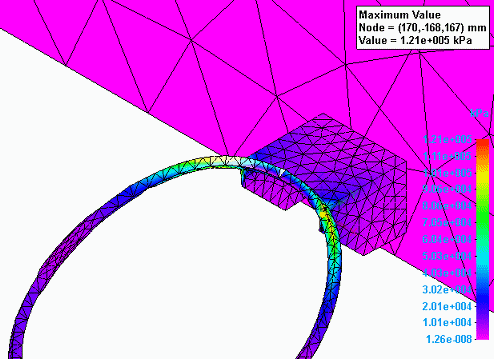
Locate the maximum stress:
-
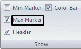
Select Color Bar tab→Show group→Max Marker.
 Tip:
Tip:You can change the text color and text size of the color bar using options in the Color Bar tab→Font group.
-
-
Close this file.
In this activity, you explore how a force applied to a basketball hoop or rim affects the hoop itself.
© 2021 UDS