Change connector region direction
Use the Edit Region Directions command to review and modify the assembly connector region direction.
In a correctly defined assembly connector, the faces and surfaces in the target region and the faces and surfaces in the source region should point towards each other.
-
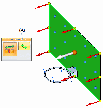
In the Simulation tree-view pane, right-click a connector and choose Edit Region Directions.
The graphics window shows the faces and surfaces constituting the target region and their individual direction indicators.
-
Modify the direction of the connector region on the target faces and surfaces by doing one of the following:
-
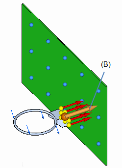
To flip the connector direction by 180 degrees for all of the faces and surfaces, click the Flip All Directions button on command bar (A) or press F on the keyboard.
-
To change the direction of individual faces and surfaces, click the direction handle (B) on that face or surface.
-
-
Press Enter or right-click to continue to the source region step.
-
Repeat to modify the direction of the connection on the source faces and surfaces of the connector.
Tip:-
To leave a region direction unchanged, press Enter or right-click to skip the step and continue.
-
You can use the Edit Region Connectors command to modify glue and no penetration connectors created automatically or manually.
-
© 2021 UDS