Using variables in part models
Using variables in part models activity
When you finish the tutorial, you will have learned how to construct a parametric model where editing the value of one or two key dimensions causes the rest of the model to update in a predictable manner. These concepts can be applied to a wide range of models, as most designs have features that are interrelated.
Launch the Using variables in part models.
Construct an extruded feature
-
Open the document ...\Program Files\UDS\QY CAD 2022\Training\seppcvt.par.
-
On the Application menu, choose Save As→Save As to save the document as a personal copy.
-
On the Save As dialog box, save the part file to a new name or location so that other users can complete this activity.
-
Choose the Home tab→Solids group→Extrude command
 .
. -
On the Extrude command bar, in the Create-From Options list, click the Coincident Plane option.

-
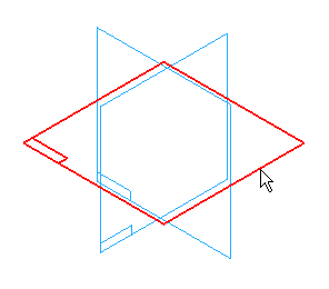
Select the reference plane shown.
Set the IntelliSketch options
-
Choose the Home tab→IntelliSketch group→IntelliSketch command
 .
. -
On the IntelliSketch dialog box, do the following:
-
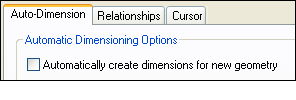
On the Auto-Dimension tab, ensure that the Automatically Create Dimensions for New Geometry option is cleared.
-
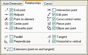
On the Relationships tab, ensure that the settings match the illustration.
-
Draw the profile
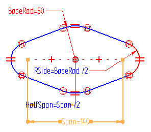
In the next few steps, draw the profile shown above.
Draw three circles, connect them with four tangent lines, trim the circles, apply relationships, place and rename several dimensions, and define formulas between several dimensions.
Draw a circle
-
Choose the Home tab→Draw group→Circle By Center Point command
 .
. -
On the Circle command bar, in the Diameter box, type 100 as the diameter of the circle, then press Enter.
-
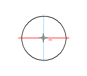
Position the cursor where the reference planes intersect, and when the midpoint relationship indicator
 is displayed adjacent to the cursor, click to define the center of the circle.
Hide all reference planes
-
Choose the Home tab→Select group→Select command
 .
. -
Right-click to display the shortcut menu, then choose Hide All→Reference Planes.
Draw another circle
-
Choose the Home tab→Draw group→Circle By Center Point command
 .
. -
On the Circle command bar, in the Diameter box, type 34 as the diameter of the circle, then press Enter.
-
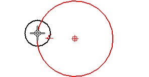
Position the cursor over the first circle, as shown, but do not click.
-
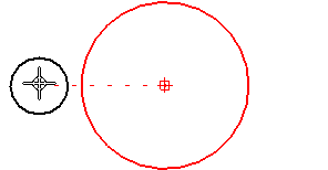
When the circle highlights, move the cursor to the left approximately as shown. When the centers of the two circles are horizontally aligned, a dashed line appears.
-
Click to define the center of the circle. A horizontal relationship should be automatically applied between the circle centers.
Draw a third circle
-
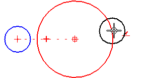
Position the cursor over the first circle, as shown, but do not click.
-
Move the cursor to the right, and when the horizontal dashed line is displayed, click to position the third circle. Again, a horizontal relationship should be automatically applied between the circle centers, as shown.
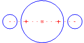
The Circle By Center Point command is still active.
Draw a line connecting the circles
-
Choose the Home tab→Draw group→Line command
 .
. -
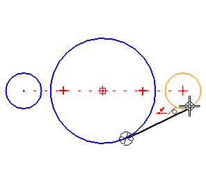
Position the cursor on the lower edge of the large circle, and when it highlights, click to place the start point of the first line.
-
Move the cursor through the intent zone so that a tangent relationship is placed between the line and the circle, and then move the cursor to locate the smaller circle on the right.
-
When the point on element and tangent relationship indicators
 are displayed, click to place the line.
 -
After placing the line, right-click to start a new line.
Draw three more lines
-
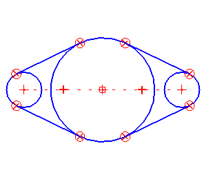
Draw three more lines to connect the top and bottom edges of the three circles, as shown.
-
Start each new line by positioning the cursor over the large circle at the approximate tangent point.
-
Draw the lines so that IntelliSketch places the tangent and connect relationships at each intersection. Later you will have the opportunity to correct any incorrect relationships.
Ensure that the lines are tangent and connected to the circles
-
Choose the Home tab→Relate group→Tangent command
 .
. -
Click the line and the circle to apply the relationship at their intersection.
-
Choose the Home tab→Relate group→Connect command
 .
. -
Click the line and the circle to apply the relationship at their intersection.
![]()
Tangent ![]() and connect
and connect ![]() relationship handles should appear at both endpoints of each line. The relationship handles overlap
relationship handles should appear at both endpoints of each line. The relationship handles overlap ![]() . These relationships should have been applied by IntelliSketch while drawing the lines.
. These relationships should have been applied by IntelliSketch while drawing the lines.
If both of these relationship handles at each endpoint are not displayed, as shown, apply them now:
Trim the interior of the profile
-
Choose the Home tab→Draw group→Trim command
 .
. -
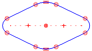
Position the cursor at point (A), as shown. Press and hold the mouse button down, then drag the mouse along the path shown. Release the mouse button at point (B).
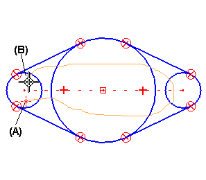
The profile is trimmed as shown below.
Make the arcs equal
-
Choose the Home tab→Relate group→Equal command
 .
. -
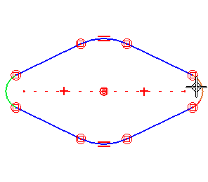
Although the two small arcs are the same size, apply an equal relationship to ensure that the arcs stay equal when making a design change later.
Select the arcs at the left and right sides of the profile to apply an equal relationship between them.
-
If a concentric relationship was not automatically applied to the top and bottom arcs when trimming the profile, apply the concentric relationship to the arcs now.
Dimension the arcs in the profile
-
Choose the Home tab→Dimension group→SmartDimension command
 .
. -
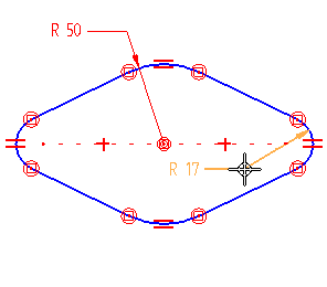
Select the arc at the top of the profile, and place the dimension as shown.
-
Select the arc at the right side of the profile, and place the dimension as shown above.
The dimension values of the arcs may be different from those shown in the illustration. These values are not important now, because later, the variable table will be used to edit the dimensions.
Because there are equal relationships between the arcs on the left and right sides and the top and the bottom of the profile, these two dimensions control the sizes of all four arcs.
Dimension the width of the profile
-
Choose the Home tab→Dimension group→Distance Between command
 .
. -
On the Dimension command bar, ensure that the Horizontal/Vertical option is set.

-
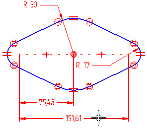
Select the center of the arc on the left side of the profile, and then select the center of the arc at the top of the profile. Place the dimension below the profile.
-
The Distance Between command is still active, ready to place another dimension in a group with the first dimension. Select the center of the arc at the right side of the profile, and place the dimension stacked with the first dimension.
Ensure that the profile matches the illustration
![]()
The profile should contain the following:
-
Equal relationships between the arcs on the left and right sides of the profile.
-
Equal relationships between the arcs at the top and bottom of the profile.
-
Concentric relationship between the arcs at the top and bottom of the profile.
-
Connect and tangent relationships between the lines and arcs at each intersection.
-
Horizontal relationships between the centers of the arcs at the sides of the profile and the arc at the top of the profile.
-
Radial dimensions on the arcs at the top and right side of the profile, and linear dimensions between the arc centers. The values of the dimensions may be different from those shown in the illustration.
Rename a variable
-
Choose the Home tab→Select group→Select command
 .
. -
Position the cursor over the 50 mm radius dimension at the top of the profile, then right-click to display the shortcut menu.
-
On the shortcut menu, click Edit Formula to display the Edit Formula command bar.
-
On the Edit Formula command bar, in the Name box, type BaseRad, then press Enter.
 Note:
Note:It is important to press Enter after typing the new variable name.
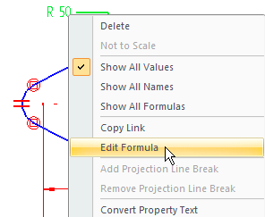
In the next few steps, define new names for the dimensions placed and use these names to define formulas between several of the dimensions.
Rename another variable and define a formula
-
Choose the Home tab→Select group→Select command
 .
. -
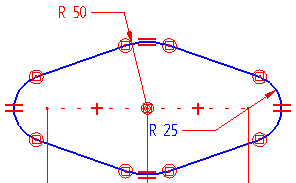
Click the radius dimension at the top of the profile, and then click
 .
.
-
Repeat the above step for the right side of the profile.
-
Position the cursor over the radius dimension at the right side of the profile, right-click to display the shortcut menu again, and then click Edit Formula.
-
On the Edit Formula command bar, in the Name box, type RSide, then press Enter.
-
In the Formula box, type BaseRad/2, then click the Accept
 button.
-
Choose the Home tab→Select group→Select command
 .
. -
In the graphic window, click to de-select the radius dimension.
Notice that the text for this dimension has changed color, and that its value has changed to be one half the value of the large radius dimension renamed to BaseRad in the previous step. The text color changed to indicate that the value of this dimension is controlled by another dimension.
Change the dimension display
-
Position the cursor over the 50 mm radius dimension, and then right-click to display the shortcut menu.
-
On the shortcut menu, click Show All Formulas.

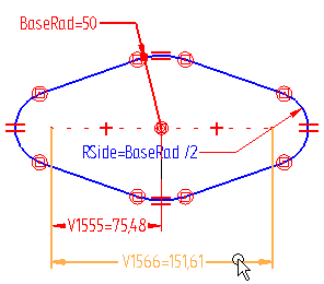
Notice that the dimension names and formula defined are displayed.
The default names for the other dimensions may be different than shown in the illustration. In the next few steps, rename these dimensions also.

Rename another variable
-
Position the cursor over the dimension shown, then double-click to display the Edit Formula command bar.
-
On the Edit Formula command bar, in the Name box, type Span, then press Enter.
-
Position the cursor as shown below, then right-click to finish renaming the dimension.

The Edit Formula command bar can also be displayed by double-clicking a dimension.
Define another formula
-
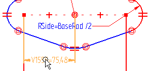
Position the cursor over the dimension shown, then double-click to display the Edit Formula command bar.
-
On the Edit Formula command bar, in the Name field, type HalfSpan, then press Enter.
-
Position the cursor over the dimension you renamed to Span as shown below, then left-click.
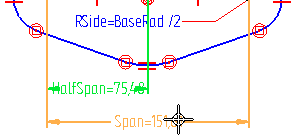
Notice that the dimension name "Span" is automatically pasted into the Formula box.
-
In the Formula box, type /2, then click the Accept
 button.
You want the value of HalfSpan to be one half the value of Span.
Change the dimensional value for Span
-
Choose the Home tab→Select group→Select command
 .
. -
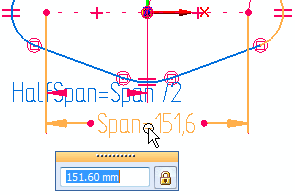
Position the cursor over the Span dimension as shown, then left-click once to display the Dimension command bar.
-
On the Dimension command bar, type 140, then press Enter.
The values of Span and HalfSpan are updated.
Finish the profile

-
Choose the Home tab→Close group→Close Sketch command
 .Tip:
.Tip:The sketch can also be closed by using the Close Sketch icon in the top-left corner of the graphics window.

Project the profile
-
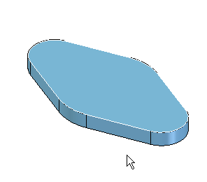
On the Extrude command bar, ensure the Finite Extent option
 is set, then in the Distance box, type 15 as the extent distance, then press Enter.
 -
Position the cursor below the profile, and click to extend the feature downward.
Finish the feature
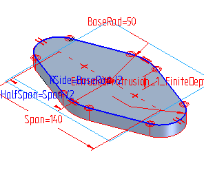
-
On the command bar, click
 .
.
Save the part
![]()
-
On the Quick Access toolbar, located at the top, left side of the application window, click the Save button
 to save the work done so far.
Construct another extruded feature
![]()
In the next few steps, construct a cylinder that protrudes above the base feature.
-
Choose the Home tab→Solids group→Extrude command
 .
.
Define the profile plane
![]()
-
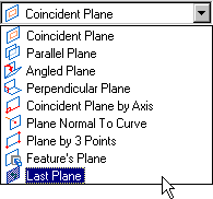
On the command bar, in the Create-From Options list, set the Last Plane option, to use the same profile plane used for the base feature.
Draw a circle
-
Choose the Home tab→Draw group→Circle by Center Point command
 .
. -
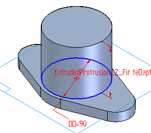
On the command bar, type 90 as the diameter of the circle, then press Enter.
-
Locate the center of the arc at the top of the profile, and click to place the center of the new circle.
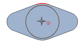
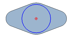
The circle is placed as shown below.
Dimension the diameter of the circle
-
Choose the Home tab→Dimension group→SmartDimension command
 .
. -
Select the circle.
-
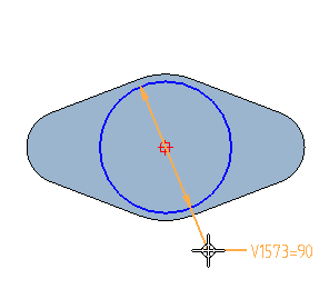
Place the diameter dimension as shown. Right-click to finish.
Rename the dimension
-
Choose the Home tab→Select group→Select command
 .
. -
Position the cursor over the dimension placed and double-click to display the Edit Formula command bar, as shown above.
-
In the Name box, type OD, then press Enter.
-
Right-click to finish renaming the dimension.
The dimension display should update as shown.

Define a formula for this dimension later that will be based on another feature to construct.
![]()
The dimension may have a different name than shown.
Finish the profile
![]()
-
Choose the Home tab→Close Group→Close Sketch command
 to close the profile view.
Project the profile
-
On the command bar, click the Finite Extent button
 .
. -
Type 80 as the extent of the protrusion, the press Enter.
-
Position the cursor above the profile, and click.
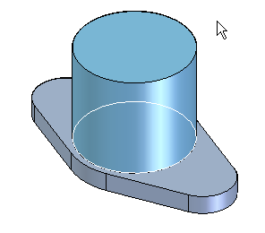
Finish the feature
-
On the command bar, click
 .
.
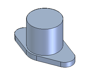
Fit the view and save the part
-
On the bottom-right side of the application window, on the Viewing Commands toolbar, choose the Fit command
 .
. -
Choose the Quick Access toolbar→Save command
 .
.
Construct a cutout
![]()
-
Construct a cutout through the center of the part.
Choose the Home tab→Solids group→Cut command
 .
.
Define the profile plane
![]()
-
On the command bar, in the Create-From Options list, set the Last Plane option, to use the same profile plane used for the previous feature.

Draw a circle
-
Choose the Home tab→Draw group→Circle By Center Point command
 .
. -
Type 60 as the diameter of the circle, then press Enter.
-
Locate the center of the cylindrical protrusion just drawn, and click to place the center of the circle.
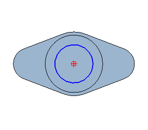
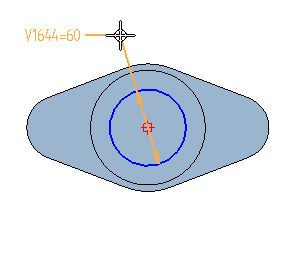
Dimension the diameter of the circle
-
Choose the Home tab→Dimension group→SmartDimension command
 .
. -
Select the circle.
-
Place the dimension as shown. Right-click to finish.
Rename the dimension
-
Choose the Home tab→Select group→Select command
 .
. -
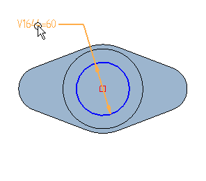
Position the cursor over the dimension placed and double-click to display the Edit Formula command bar, as shown above.
-
In the Name box, type ID, then press Enter.
-
Right-click to finish renaming the dimension.
The dimension display should update as shown below.

Change the dimension display
-
Choose the Home tab→Select group→Select command
 .
. -
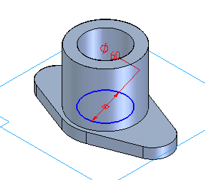
Position the cursor over the 60 mm diameter dimension, and then right-click to display the shortcut menu.
-
On the shortcut menu, click Show All Values.
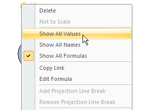
Notice that only the dimension value is displayed.
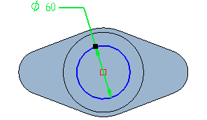
Finish the profile
![]()
-
Choose the Home tab→Close group→Close Sketch command
 .
.
Project the profile
-
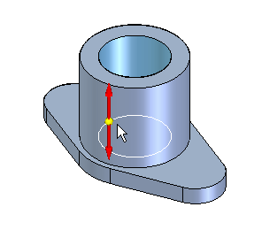
On the command bar, click the Through Next button
 .
. -
To extend the profile symmetrically, position the cursor as shown, then click when the double arrow is displayed.
Finish the feature
-
On the command ribbon bar, click
 .
.
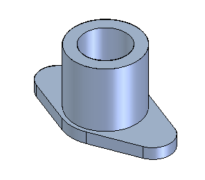
Save the part
-
Choose Quick Access toolbar→Save
 .
.
Construct a hole pattern
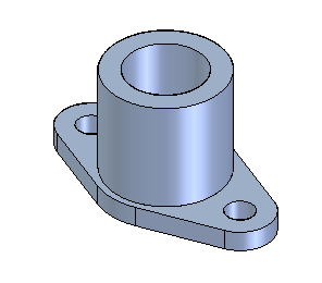
Construct two holes through the base feature.
-
Choose the Home tab→Solids group→Hole command
 .
.
Define the profile plane
-
On the command bar, in the Create-From Options list, set the Last Plane option, to use the same profile plane used for the previous feature.

Set the hole options
-
On the command bar, click Hole Options
 .
. -
In the Hole Options dialog box, set the following hole options:
-
Set the Type to Simple

-
Set the Extents to Through Next

-
Set the Diameter to 22 mm, then click OK.
-
![]()
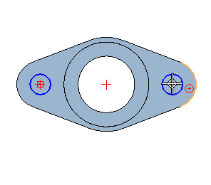
Draw two holes
-
Move the cursor across the small arc on the left side of the part, and then locate its center.
-
Click to draw the hole at the center of the arc.
-
Draw another hole at the center of the arc on the right side of the base feature, as shown.
Finish the profile
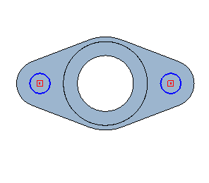
-
Choose the Home tab→Close group→Close Sketch command
 .
.
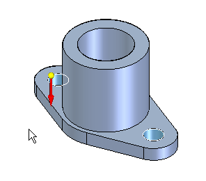
Project the profile
-
Position the cursor below the profile to extend the holes down, and click.
Finish the feature
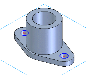
-
On the command bar, click Finish.
Save the part
-
Choose Quick Access toolbar→Save
 .
.
Display the variable table
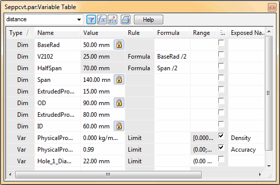
Use the QY CAD variable table to display, define, and manipulate design variables and functional relationships between the variables. Using the variable table, define additional relationships between the dimensions placed on the part. These relationships allow changes to the size and shape of the entire part by editing one dimension.
-
Choose the Tools tab→Variables group→Variables command
 .
.
The software displays the variable table window.
The variable table may need to be resized and relocated, or adjust the view to see the part model and the variable table properly.
Set the variable table filter
-
Along the top of the variable table menu bar, click Filter
 .
. -
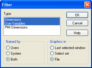
On the Filter dialog box, do the following:
-
Set the Named By option to Both.
-
Set the Graphics In option to File, then click OK.
-

The variable table has a filter that allows control of which dimensions and variables it displays. Set the filter to display all of the dimensions placed on the part.
View the variables the system has named
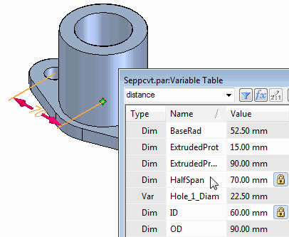
Notice that the variables renamed and the formulas defined earlier in the tutorial are listed in the variable table.
Also notice that QY CAD assigned a unique variable name to each dimension placed on the part and for the dimensions that were created automatically. For example, the extent values for the protrusions and the hole diameter variable.
Some of the names may be different from those shown in the illustrations. The variable table displays each of these variables and their values in separate rows. Move the cursor across the rows of the variable table, and notice that the corresponding dimensions are highlighted in the part model.
Rename a variable and define a formula
-
Move the cursor over the rows of the variable table until the height of the circular protrusion is highlighted. The dimension value should be 80 mm.
-
When locating this dimension, select the name cell for this variable, then type Height as the new name for the variable, and press Enter.
Note:It is important to press Enter each time an edit is made to a variable table cell.
-
Move the cursor over to the formula cell for this variable, select the cell and then type OD as the formula and press Enter.
Notice that the value for Height changes in the variable table to 90 mm, and the model updates.
For this part, the height of this protrusion should always be equal to the outside diameter. The variable table should now look similar to the illustration below.
Also notice that the background color for the value cell for the Height variable changes color. The new color indicates that the value for this variable is now driven by the formula defined.

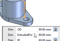
The variable table can also be used to rename variables and define formulas using.
Rename another variable
-
Move the cursor over the row of the variable table that highlights the dimension of the height of the first protrusion (15 mm).
-
Select the name cell for this variable, and rename the variable Thickness. Be sure to press Enter.
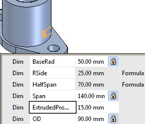
Rename the hole variable and define a formula
-
Select the name cell for this variable, and rename the variable MtHole, as shown. Be sure to press Enter.

-
Move the cursor over to the formula cell for this variable, select the cell and then type: Thickness*1.5 as the formula and press Enter.
For this part, the hole diameter should be equal to 1.5 times the thickness of the first protrusion.
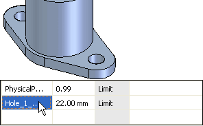
In the variable table, locate the variable table name entry for the hole diameter variable. The variable value is 22 mm.
For this variable, there is no corresponding graphical dimension, so a dimension will not highlight in the graphic window.
Define a formula
-
In the variable table, select the formula cell for the outside diameter dimension (OD) of the protrusion.
-
In the Formula column for the variable, type: ID + (Thickness*2) as shown below. Press Enter.
The variable table should appear similar to the illustration below.

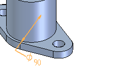
Define a formula that relates the outside diameter of the protrusion at the top of the part to its inside diameter (the ID variable defined previously) and the thickness of the bottom of the part (Thickness).
Define more formulas
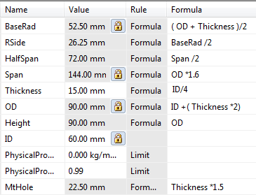
-
Define the formulas shown for each of the following variable values. Press Enter after typing each formula:
| Variable Value | Name | Formula |
| Large Radius on the base feature | BaseRad | (OD+Thickness)/2 |
| Distance between the two small holes | Span | OD*1.6 |
| First protrusion thickness | Thickness | ID/4 |
Edit a dimension through the variable table
-
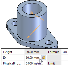
In the variable table, select the row of the variable named ID, and set its value to 50 by typing 50, and pressing Enter.
Notice that all of the dimensions whose formulas are derived from the value of ID change in response to the new value.
Parts like this, whose shapes and sizes can be controlled by editing the value of a variable, are sometimes called parametric.
When constructing parts in QY CAD, take advantage of the capabilities of the variable table to rename variables to more logical names and to define formulas that relate design variables to one another.
Display the Variable Rule Editor dialog box
-
Position the cursor as shown in the illustration, adjacent to the row for the ID variable, then click to select the row.
Notice that the entire row is selected and that the Variable Rule Editor button
 on the dialog box is now active.
 -
Click the Variable Rule Editor button
 to display the Variable Rule Editor dialog box.

In the next few steps, use the Variable Rule Editor dialog box to define a set of rules for the ID variable, then edit the variable using PathFinder and the Dimension command bar.
Defining rules for variables restricts design changes to a more controllable set of values.
Define the rules for the ID variable
-
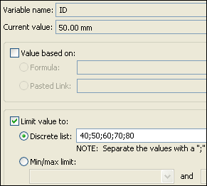
Set the following options:
-
Check the Limit Value To check box.
-
Set the Discrete List option.
-
In the Discrete List box, type 40;50;60;70;80
-
-
Be sure to separate each numeric value with a semicolon, as shown.
-
Click OK to accept the changes and dismiss the dialog box.
You have specified that the only valid values for the ID variable are 40; 50; 60;70;80 millimeters.
Take a few moments to observe the options on the dialog box.
Dismiss the variable table
-
On the Variable Table dialog box, click the X button
 to dismiss the variable table.
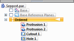
Select the Cutout 1 feature in Feature PathFinder
-
Choose the Home tab→Select group→Select command
 .
. -
In PathFinder, select the Cutout 1 feature, as shown.
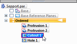
-
On the Select edit handle, click the Dynamic Edit button
 .
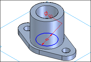
.Notice that the profile, reference plane, and dimension for the Cutout 1 feature are displayed in the graphic window.
Edit the ID variable
-
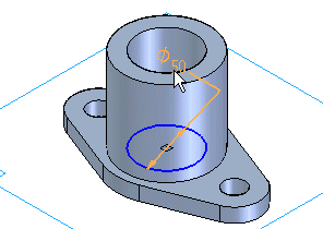
In the graphic window, position the cursor over the 50 mm diameter dimension, and click to select it. Be sure to position the cursor over the dimension value, as shown, and not over the dimension leader line.
-
On the dimension edit list, click the arrow adjacent to the current dimension value box, as shown.
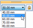
Notice that a list of the valid values defined on the Variable Rule Editor dialog box is displayed. These are the only values to specify for the variable using the Dimension command bar.
This prevents applying inappropriate values for this dimension variable.
-
Select the 60 mm value in the list, and notice that the model updates.
Save the part
-
Choose the Viewing commands toolbar→Fit command
 .
.
-
Choose the Quick Access toolbar→Save command
 .
.
© 2021 UDS