Activity: Create a swept feature
Create a swept feature
In this activity, learn how to arrange the workspace, use various swept options, understand the swept command bar, and create a simple swept feature.
Launch the Activity: Create a swept feature.
Open the activity part file
-
Open ...\Program Files\UDS\QY CAD 2022\Training\seppcsw.par.
-
On the Application menu, choose the Save As→Save As command.
-
On the Save As dialog box, save the part file to a new name or location so that other users can complete this activity.
Arrange your workspace
-
If there are any other QY CAD files open, close them now.

Start the Swept Protrusion command
-
Choose the Home tab→Solids group→Sweep command
 .
. -
If the Sweep Options dialog box does not display, on the Swept Protrusion command bar, click the Options button
 .Note:
The dialog box is automatically displayed only if the Show This Dialog When The Command Begins option is selected.
![]()
Examine the Sweep Options dialog box
-
Take a few moments to examine the various options on the Sweep Options dialog box.
In the next few steps, construct a simple one path and one cross section swept feature. Later, explore other options.
-
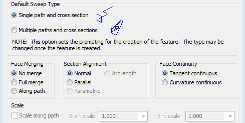
On the Sweep Options dialog box, make sure the Single Path and Cross Section option is selected and the other options match the illustration, then click OK.

Examine the command bar
-
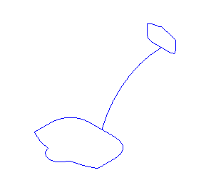
In the Path step, draw or select a sketch representing the path that a cross section will be swept along to create the protrusion.
-
In the Cross Section Step, draw or select a sketch representing the cross section that will be swept along the path.

The default option for creating the path of the protrusion is by selecting elements from a sketch. If there were solid features in the file, model edges could be selected to define the path.
Another option is to draw the path.
The training file has several sketches to help finish the tutorial more quickly.

The command bar helps guide and provides options while working through commands. Command bars change as the command proceeds, so they always display information and choices about what is happening right now. Beginning at the left side, examine the command bar and notice the current options:
Select an element from Sketch 1
-
If it is not already selected, on the command bar, click the Select From Sketch/Part Edges option, as shown below.

-
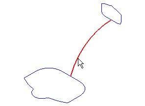
Position the cursor over the arc in Sketch 1, as shown. When the arc highlights, click to select it.

-
Right-click to accept the selected sketch. The cursor must be in the graphics window when right-clicking.
The sketch can also be accepted by clicking the Accept
 button on the command bar.
Define a cross section profile
-
The command bar shows that the next step is defining the cross section that will be swept to construct the protrusion.

-
On the command bar, choose the Select From Sketch/Part Edges option.
-
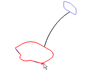
Position the cursor at the location shown and notice that a point is displayed at the sketch vertex nearest to the cursor.

This point represents the start point for the cross section. The selected start point is important when there is more than one cross section in the feature. Learn more about this later.
-
Click when the start point on the computer matches the illustration.
Observe the feature
![]()
All of the basic steps for constructing the swept protrusion are complete. The sketch was swept along a path to form a solid feature.
Notice that the command bar displays sections to edit each step, defining the path and defining the cross section, taken in constructing the protrusion. An Axis step is also available for certain types of swept features, which will not be covered in this tutorial.
Before finishing, in the next several steps of the tutorial, learn how to edit the information you provided in previous steps and create a more sophisticated feature with two cross sections.
© 2021 UDS