Activity: Construct features in the synchronous environment
Construct features in the synchronous environment
In this activity, create synchronous features using the Extrude, Round, Draft, Hole, and Mirror commands.
Launch the Activity: Construct features in the synchronous environment.
Open the activity file
-
Open ...\Program Files\UDS\QY CAD 2022\Training\seppas3.par.
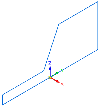
Save a new version of the file
-
On the Application menu, choose the Save As→Save As command.
-
In the Save As dialog box, save the part to a new name or location so that other users can complete this tutorial using the original part file.
Get to know the part

Use the PathFinder tool in this tutorial. The PathFinder location on the computer may be different than the illustration. Because of the space limitations of the tutorial window, PathFinder displays as floating.
The model contains a synchronous sketch and an ordered construction surface. Use these elements to construct other features. Use the sketch (named base profile) to create the synchronous base feature.
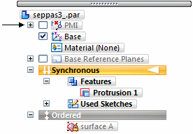
Notice that both the Synchronous and Ordered environment bars appear. When a model contains both synchronous and ordered features, then both environment bars appear in PathFinder.
-
A model that contains both feature types opens in the ordered environment.
-
If a model contains only ordered features, then the file opens in the ordered environment.
-
If a model contains only synchronous features, the file opens in the synchronous environment.
Construct a synchronous base feature
-
Switch to the synchronous environment by either clicking the Synchronous bar in PathFinder or by right-clicking in the part window and choosing the Transition to Synchronous command from the shortcut menu.
-
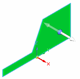
The Select command is active. Select the region defining the base feature cross section.
-
On the Extrude command bar, click the Symmetric extent option
 .
. -
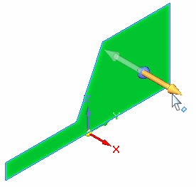
Click the extrude handle.
-
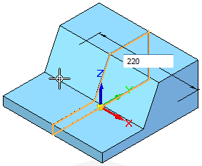
In the Dynamic Edit box, type 220 and then press Enter.
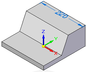
-
Turn off the display of the PMI dimensions by clearing the check box in PathFinder.
Construct a synchronous boss feature
-
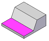
On the Home tab→Draw group, choose the Line command. Move the cursor to the part face that matches the one highlighted in the following illustration, and press F3 to lock the sketch plane to that face.
-
Change the view to a sketch view. On the View tab→Views group, choose the Sketch View command.
-
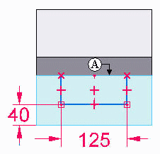
The Line command is active. Draw an open sketch on the highlighted face. Align the midpoint of the horizontal line with the midpoint on edge (A). Dimension the sketch as shown.
 Note:
Note:Align the midpoint of the horizontal line with the midpoint of the part edge (A). On the Sketching tab→Relate group, choose the Horizontal/Vertical command
 . Select the midpoint of the horizontal sketch line and then select the midpoint of the part edge (A). If the relationship handles do not appear, in the Relate group, choose the Relationship Handles command
  .Note:
Sketch element relationships are key to creating a robust model that behaves predictably when edited. To learn more, view Sketching videos available in the QY CAD videos collection.
-
After placing the dimensions, edit each dimension. Unlock the dimension value by clicking the lock in the Dimension Value Edit dialog box.


-
Press Ctrl+I to change the view to an isometric view.
-
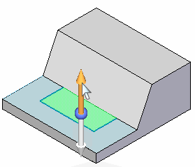
Select the region created by the open sketch.
-
Click the steering wheel handle. Turn off the Symmetric Extent option. Type 45 in the Dynamic Edit box and then press Enter.

-
Turn off the display of the PMI dimensions by clearing the check box in PathFinder.
Add rounds to corners
-
Choose the Home tab→Solids group→Round command.

-
Select the two edges shown. For the radius value, type 25 in the Dynamic Edit box and then press Enter.


Add rounds to the synchronous base feature
-
Choose the Round command.
-
Select all edges shown on the features. Type 5 in the Dynamic Edit box and press Enter.


Add a circular boss
-

Draw a 25 mm diameter circle on the sketch plane shown. Make the sketch circle concentric to the rounded corner.
-
Extrude the circular region a distance of 7 mm. Add a 3 mm round to the top edge of the boss.

Mirror copy the circular boss and round
-
In PathFinder, turn on the display of the Right (yz) base reference plane. Use this as the mirror plane because the part is symmetric about this plane.

-
In PathFinder, select the last protrusion and round features.
Note:To select multiple features, hold the Ctrl key while selecting features.

-
On the Home tab→Pattern group, choose the Mirror command
 .
. -
Select the Right (yz) reference plane and then press Escape to end the mirror command.


Add synchronous hole features
-
On the Home tab→Solids group, choose the Hole command
 .
. -
On the Hole command bar, click the Hole options button
 .
. -
Enter Hole settings: Type=simple
 , Standard=ISO Metric, Size=10, Hole extent=Through next. Click OK.
 -
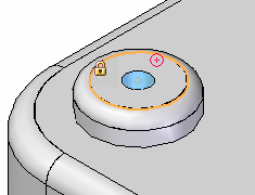
Position the cursor over the top face of the circular boss and click when the center point icon appears.
-
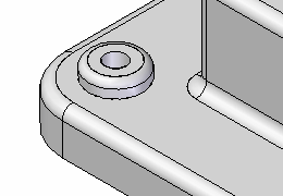
Choose the Select tool and then press Escape to end the Hole command.
-
Mirror the hole about the Right (yz) plane.
| Activity: Construct features in the ordered environment |
© 2021 UDS