Activity: Connecting blocks with connectors
Place and edit connectors
In this activity learn how to place and edit connectors that connect the blocks to other components on a wiring diagram.
Launch the Activity: Connecting blocks with connectors.
Start the Connector command
Connectors are a type of annotation used to connect blocks and other 2D elements and objects in schematic diagrams, flow charts, and other 2D drawings.
They have built-in intelligence to easily connect and disconnect them from blocks and other connectors.
Five connector shapes are available:
-
Line
-
Jump
-
Gap
-
Corner
-
Step
Use the Start and End options to specify the end conditions for a connector.
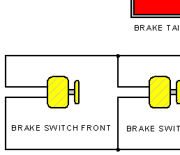
-
Choose the Home tab→Annotation group→Connector command
 .
.QY CAD displays the Connector command bar to use to define the connector options.
Place a jump connector
-
On the Connector command bar, set the following options:
-
Shape: Jump
-
Start: Blank
-
End: Blank
-
Jump radius/gap: 0.8
-
-
Move the cursor to the end point of the connector line, as shown, and when the endpoint relationship indicator
 appears next to the cursor, click.
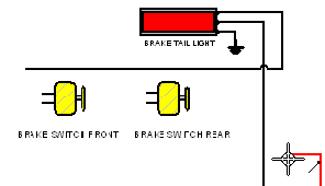
-
Move the cursor to the approximate location shown next, and then click.
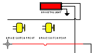
-
Right-click to restart the Connector command.
Observe the jump connector
-
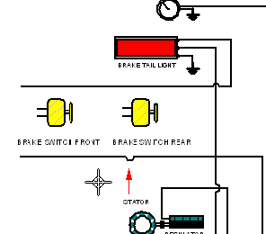
Notice that the jump location for the connector is not positioned correctly.
In later steps, the jump connector will be repositioned.
Place a corner connector
-
Right-click to restart the Connector command.
-
On the Connector command bar, set the following options:
-
Shape: Corner
-
Start: Blank
-
End: Blank
-
-
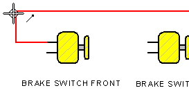
Move the cursor to the end point of the line on the block shown, and when the endpoint relationship indicator
 appears next to the cursor, click.
-
Move the cursor to the end point of the connector line shown, and when the endpoint relationship indicator
 appears next to the cursor, click.
-
If the corner connector does not match the previous illustration, on the command bar, click the Flip button to change its orientation.
-
Right-click to restart the Connector command.
Place another connector
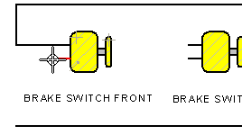
Another corner connector is needed to finish connecting the front brake switch block.
-
Move the cursor to the endpoint of the line on the block shown, and when the endpoint relationship indicator
 appears next to the cursor, click.
-
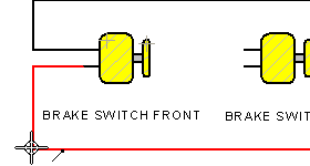
Move the cursor to the end point of the connector line shown next, and when the endpoint relationship indicator
 appears next to the cursor, click.
-
Right-click to restart the Connector command.
Place another connector
Two more corner connectors are required to hook in the back brake switch block.
For these connectors, define a different end condition.
-
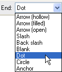
On the command bar, in the End list, select the Dot option.
The Dot option specifies that the second end of the connector will have a dot terminator shape.
-
Move the cursor to the end point of the line on the block shown, and when the endpoint relationship indicator
 appears next to the cursor, click.
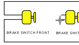
-
Move the cursor to the connector line shown, and when the connector line highlights, click.
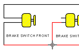
-
Right-click to restart the Connector command.
Place another connector
-
Move the cursor to the end point of the line on the block shown, and when the endpoint relationship indicator
 appears next to the cursor, click.
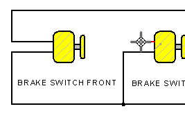
-
Move the cursor to the connector line shown, and when the connector line highlights, click.
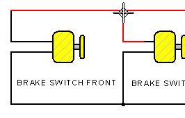
-
Right-click to restart the Connector command.
Reposition the jump connector
Reposition the jump location on the jump connector placed earlier.
-
Choose Home tab→Select group→Select
 .
. -
Position the cursor over the jump connector created earlier, as shown, and then click to select it.
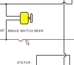
-
Position the cursor over the jump handle, as shown.
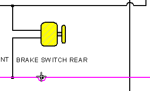
The cursor changes shape when it is over the handle.
-
Press and hold down the left mouse button, drag the cursor to the right until the vertical connector line highlights, as shown, and then release the mouse button.
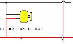
-
With the jump connector still selected, on the command bar, click the Flip button to flip the jump arc direction.
The jump arc location is now attached to the vertical connector line. If the vertical connector line moves, the jump also moves.
Disconnect a connector
Connectors can be disconnected from the elements to which they are connected.
-
Choose Home tab→Select group→Select
 .
. -
Position the cursor over the connector, as shown, and then click to select it.
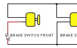
QY CAD displays the connector in the Select color and displays handles at both ends of the connector.
The end point handles are different colors, making it easier to change the terminator style for one end of the connector.
-
Position the cursor over the end point handle, as shown, hold down the left mouse button, drag the handle away from the connection point, and then release the mouse button.
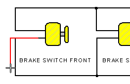
The connector disconnects from the element.
Reconnect the connector
Use the same technique used in the previous step to reconnect the connector.
-
Verify that the Select command
 is still active.
 -
Position the cursor over the end point handle, hold down the left mouse button, drag the handle until it is on top of the end point of the adjacent connector, as shown, and then release the mouse button.
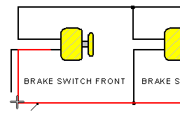
The connector reconnects to the adjacent connector.
-
To clear the selection of the elements, click in empty space.
Move a block
Move a block and observe how the connectors and callouts also move.
-
Choose Home tab→Select group→Select
 .
. -
Position the cursor over the block shown next, hold down the left mouse button, and then drag the cursor up and down.
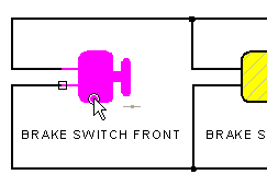
The block, connectors, and callout move as a unit.
-
Move the block back until it is approximately in the original position and then to exit the command, press Escape.
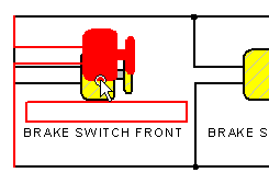
Fit and zoom in
Change the shape for a connector.
-
On the Viewing Commands toolbar, click Fit
 .
. -
On the Viewing Commands toolbar, click Zoom Area
 .
. -
Click once above and to the left of the area shown, and then click again below and to the right.
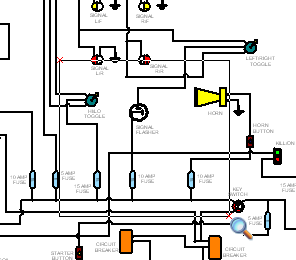
The view zooms into the area enclosed by this rectangle.
-
Right-click to exit the Zoom Area command.
Change the shape for a connector
-
Choose Home tab→Select group→Select
 .
. -
Position the cursor over the connector, as shown, and then click to select it.
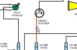
-
On the command bar, in the Shape box, select the Jump option.
-
On the command bar, in the Jump radius/gap box, set the radius value to 0.8, and then press Enter.
-
To clear the selection of the connector, click in empty space.
QY CAD changes the connector to the Jump type and automatically determines the proper jump location, as shown.
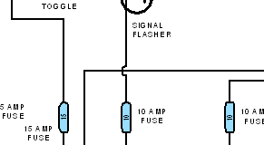
-
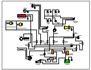
On the Viewing Commands toolbar, click Fit
 .
.
Place a block list table
Create a block list table from all of the blocks on the drawing sheet.
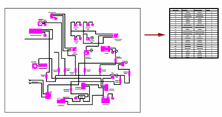
-
Choose Home tab→Tables group→Block Table command
 .
.The software selects and highlights all the blocks on the sheet and also displays the Block Table command bar. Blocks can be removed from the selection set using the Add or Remove Blocks button
 . The Properties button
  can be selected to make changes to the format and appearance of the block table before being placed.
 -
On the Block Table command bar, ensure that the Auto-Balloon option
 is selected, and then click Accept
  .
.The software displays an outline of the block table on the sheet.
-
Move the cursor to position the table at a desired location, and then click.
-
On the Quick Access toolbar, click Save
 .
.
For more information about block tables, see the Block tables help topic in Parts lists and tables.
© 2021 UDS