Activity: Create a fillet weld feature
Create a fillet weld feature
In this activity you will learn how to create a fillet weld feature.
Launch the Activity: Create a fillet weld feature.
Open the activity file
-
Open ...\Program Files\UDS\QY CAD 2022\Training\seaabwd.asm
Arrange your work space
![]()
-
If you have any other QY CAD files open, close them now.
Save and name the file
-
Click the Application button
 to open the Application menu.
 -
On the Application menu, click Save As→Save As
 .
. -
On the Save As dialog box, in the File name box, save the part to a new name or location so that other users can complete this tutorial using the original part.
-
Click Save.
Specify the assembly is a weldment assembly
-
Choose the Tools→Model→Weldment Assembly command
 .
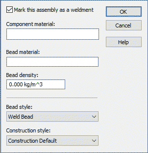
. 
-
Set the Mark this assembly as a weldment option.
-
Ensure the Bead Style is set to Weld Bead.
-
Click OK.
You use this dialog box to specify the assembly document is a weldment assembly. This activates commands and options that allow you to define weldment properties and features.
Activate the parts in the assembly
-
Ensure PathFinder is displayed.
-
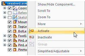
In PathFinder, position the cursor over the entry for seaabwd.asm, as shown, then right-click to display the shortcut menu.
-
On the shortcut menu, choose Activate.
The display in PathFinder updates to indicate that all the parts are active.
To ensure that your display matches the tutorial illustrations, you will activate all the parts in the assembly. Several factors determine whether or not all parts within the assembly are active on your computer.
Prepare to construct a fillet weld
-
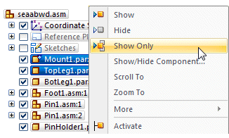
In PathFinder, position the cursor over the Mount1.par component, then click the left mouse button to select it.
-
Hold the Ctrl key down, position the cursor over the TopLeg1.par component, then left-click to select it.
-
With both components selected, right-click to display the shortcut menu, then choose Show Only.
The remaining assembly components are hidden in the graphics window.
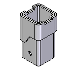
In the next few steps, you will construct a fillet weld between two assembly components. First you will hide the other components of the assembly.
Rotate the view
-
On the Viewing commands toolbar, located at the bottom-right side of the application window, click Rotate
 .
. -
In the graphics window, select the axis shown.
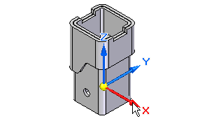
-
On the Rotate command bar, in the Rotation Angle box, type 180, and then press Enter.
-
On the Rotate command bar, click Close.
The view is rotated as shown.
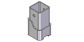
Fit the view
-
On the Viewing commands toolbar, click Fit
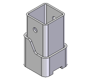
 to fit the graphics within the view.
Your display should match the illustration.
Zoom in closer
-
On the Viewing commands toolbar, click Zoom Area
 .
. -
Click above and to the left, as shown, and then again below and to the right. This defines a rectangle that becomes the new view area.
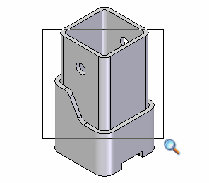
-
Right-click to end the Zoom Area command.
Define the fillet weld properties
-
Choose the Features→Assembly Weld Features→Fillet Weld command
 .
. -
If the Fillet Weld Options dialog box does not automatically display, on the Fillet Weld command bar, click Options
 .
.
-
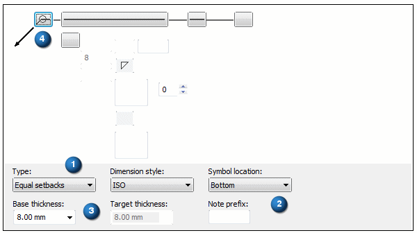
Set the Type option (1) to Equal Setbacks.
-
Set the Symbol Location option (2) to Bottom.
-
In the Base Thickness box (3) , type 8.
-
Set the All Around symbol option (4)
 .
. -
Click OK.
On the Fillet Weld Options dialog box, set the following options:
Select the base surfaces for the fillet weld
-
On the command bar, ensure that the Select option is set to Chain.
-
Move the cursor
 slowly over the model, and notice how the faces of the model highlight.
 -
Position the cursor exactly over the face shown highlighted in the illustration, stop moving the mouse for a moment, and notice that the cursor image changes
 to indicate that multiple selections are available.
 -
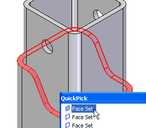
Right-click to display the QuickPick tool. Move the cursor over the different entries in QuickPick, and notice that different faces of the model highlight.
-
Use QuickPick to highlight the face set shown, and then left-click to select it.
-
On the command bar, click Accept
 .
.
Select the target surfaces
-
On the command bar, ensure that the Select option is set to Chain.
-
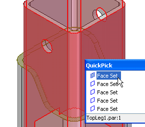
In the graphics window, use QuickPick to select the set of faces shown.
-
On the command bar, click Accept
 .
.
Finish the fillet weld
-
On the command bar, click Preview.
-
On the command bar, click Finish.
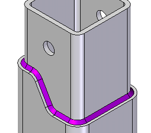
Notice that the fillet weld displays in a different color than the parts in the assembly. Fillet welds display in the active Weld Bead color.
Review the Assembly Features section in Assembly PathFinder
-
Choose Home→Select→Select
 .
. -
In PathFinder, click the "+" symbol adjacent to the Assembly Features collection.

Notice that an entry for the fillet weld feature you constructed is displayed.
© 2021 UDS