Analyze the deviation between two objects
-
Choose Reverse Engineering tab→Inspect group→Deviation Analysis
 .
. -
Click a reference object. You can use the Select option to set the reference object to a face, feature, or body.
-
Click Accept
 .
.
-
Click a test object. You can use the Select option to set the test object to a face, feature, or body.
Note:Both the reference object and test objects cannot be B-Rep bodies. One must be a mesh body.
-
Click Accept
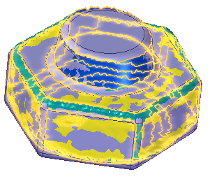
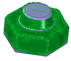
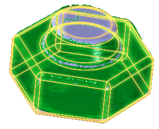
.You are placed in the Results step, which displays the color map of the deviation between the two bodies.
-
On the Deviation Analysis command bar, click the Options button
 .
. -
On the Deviation Analysis Settings dialog box, set the options for the analysis and then click Close.
After completing the analysis, you can do either of the following:
-
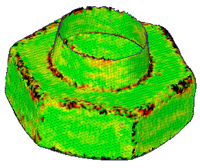
To display the maximum and minimum value markers on the model, click the Show Max and Min markers button
 .
. -
to display the Deviation Analysis dialog box that contains information for the analysis, click the Show Results Information Dialog button
 . The information is available in text so that you can copy it and use it in reports.
© 2021 UDS