Connector enhancements for frame models
Previously when you created a simulation study of a structural frame model, rigid link connectors between frame members were only generated automatically. Automatic link generation did not consider all cases where rigid links were needed, such as for disjoint beams. Sometimes rigid links were generated where they were not needed, but the connectors were not editable.
QY CAD Simulation now provides several enhancements for creating and modifying rigid link connectors in frame simulation models:
-
When creating a simulation study for a frame model, the Connector Options section of the Create Study dialog box contains a new option to specify a Maximum rigid link length. This value is used to generate rigid links between beam curves automatically.
-
You can automatically create rigid link connectors on the entire frame model using the improved Simulation tab→Rigid Links group→Auto command
 .Note:
When you open a legacy beam study of a frame model, notice the rigid links that were created previously with the Auto command are displayed in the Simulation pane. To take advantage of the enhanced rigid link creation algorithm, we recommend you either create a new study using the automatic link creation method, or delete the legacy rigid links in your existing study and recreate them using the Auto command.
-
You can manually create rigid links between two beam curves using the new Simulation tab→Rigid Links group→Manual command
 .Example:
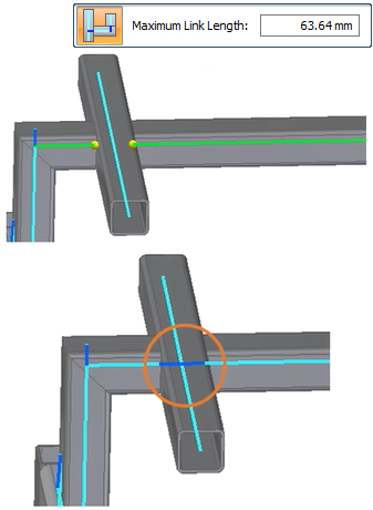
-
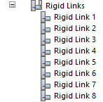
A new Rigid Links node is now available in the Simulation study navigator pane. Individual rigid links are also listed in QuickPick.
-
You can highlight individual rigid links on the model, and use shortcut commands to Delete or Rename rigid links.
-
For more information, see:
© 2021 UDS