Define rigid links manually
Use the Manual command  to add a rigid link to a beam model when:
-
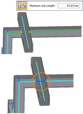
An automatic rigid link was improperly created. You can delete the connector and create a new rigid link.
-
You added, trimmed, or relocated a beam in a previously solved study. Rather than recreating the study, you can add new rigid links in the locations where they are needed to connect the beam curves.
Add a rigid link using the Manual command
-
Select the Simulation tab→Rigid Links group→Manual command
. The Manual rigid link connector command is not available in thermal studies, because rigid links do not participate in the transfer of thermal loads.
-
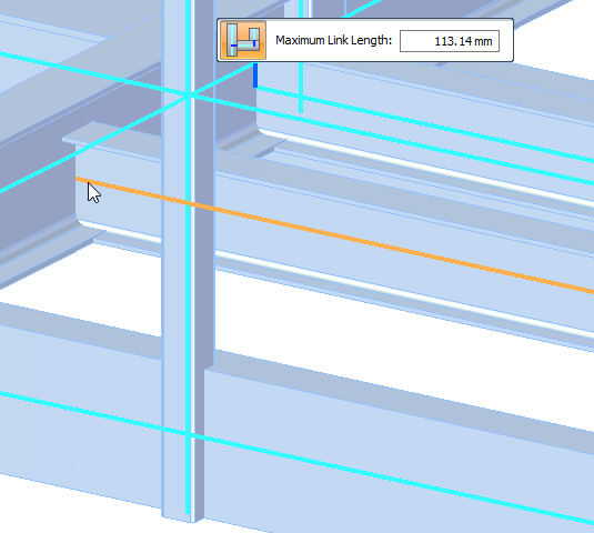
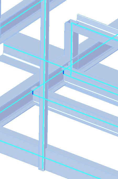
Select the source beam for the rigid link connector by selecting its blue beam curve.
-
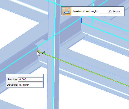
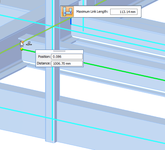
On the source beam curve, click a connection point for the rigid link. By default, the end point of the beam curve is selected, but you can specify a different connection point by hovering over points along the source beam curve until the Position box and the Distance box display the values you want to use. Click to define that point.
-
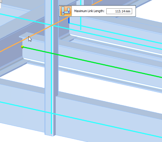
Select the target beam curve for the rigid link connector.
-
On the target beam curve, specify a second connection point for the rigid link.
-
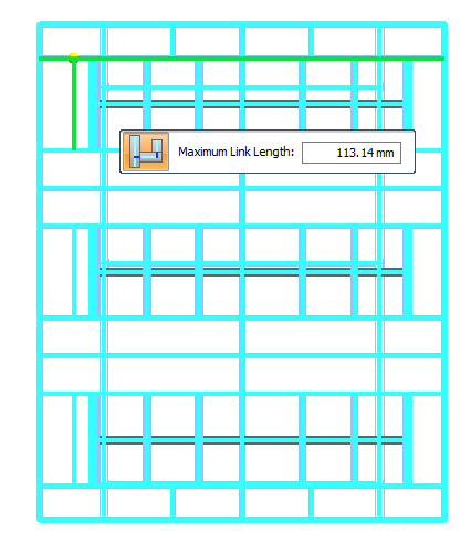
On the command bar, review and optionally change the Maximum Link Length value for the connector between the source and target beam curves.
Tip:The displayed value is equal to the length of the largest beam cross-section. This is the same value that is displayed in the Create Study dialog box, in the Connector Options section, when you create a new beam study.
-
Right-click or press Enter to add the rigid link connector.
© 2021 UDS