Create a 3D PDF template
You can use the Template Editor to create custom layouts for your 3D PDF template files (*.dft). The Template Editor opens in the familiar QY CAD Draft environment with working and background sheets, a subset of QY CAD drafting commands, and template layout commands.
You can define the 3D PDF layout starting from a blank template or by editing an existing template.
The Template Editor command is not available in the Teamcenter-managed environment.
The commands on the PMI tab→3D PDF Publishing group are only available with a QY CAD Model Based Definition license.
Open a template file and specify sheet orientation
3D PDF templates are draft files (*.dft) with a special 3D PDF template property flag.
-
To create a new template—In a part, sheet metal, or assembly document, select the PMI tab→3D PDF Publishing group→Template Editor command
 . This command creates a template file with a default name, for example 3D PDF Template1.dft.
 The empty template sheets are oriented in landscape format. Use the Application menu→Settings→Sheet Setup command to set the size and orientation of the background sheet, and then apply that to all the working sheets in the template. For more information, see Drawing sheets.
-
To customize a template—From the Application menu, browse to and open a 3D PDF template in the \Program Files\UDS\QY CAD 2022\Template\3D PDF Publish folder (*.dft). Select one of the 3D PDF templates delivered with QY CAD, based on what type of model you want to publish and how you want the 3D PDF pages to be oriented.
-
For part and sheet metal files, choose Part_Landscape.dft or Part_Portrait.dft.
-
For assembly files, choose Assembly_Landscape.dft or Assembly_Portrait.dft.
-
Add sheets to the template
Each working sheet in a template file corresponds to one page in the 3D PDF. The default 3D PDF templates provided with QY CAD contain two working sheets (two pages in published output). You can insert more working sheets in the template if you want more pages in the 3D PDF.
The single background sheet contains the information and images that you want to appear on each page of the published 3D PDF.
-
In the sheet tab tray at the bottom of the template document, use the Insert Sheet command to add one or more pages.
-
The sheet order in the sheet tab tray is the page order in the output. You can use the Reorder shortcut command tabs in the sheet tab tray to reorder them.
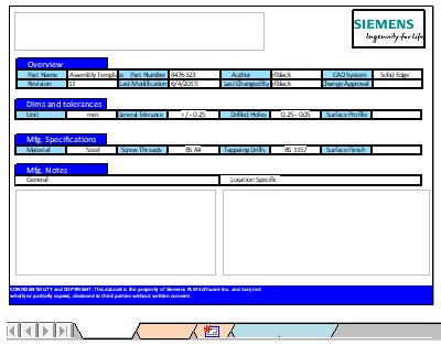
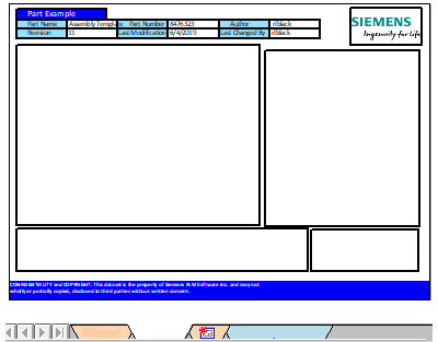
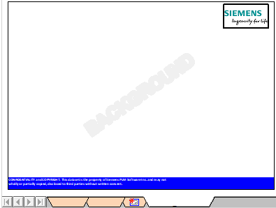
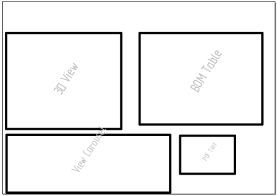
Refer to the following suggestions for how you can organize content areas on different sheets. The images show simplified 3D PDF template examples, not the templates delivered in QY CAD.
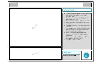
Sheet 1 sheet layout—Make the first sheet the cover sheet. Add titles to identify the information in each section, such as Overview, Dimensions & Tolerances, Manufacturing Specifications, and Manufacturing Notes (General, Location Specific).
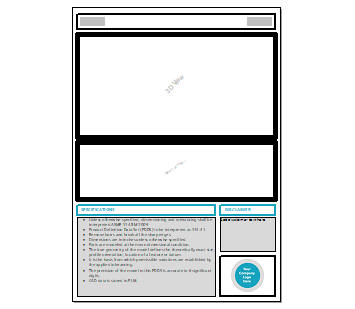
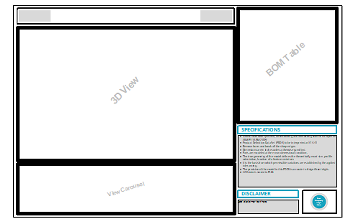
Sheet 2 sheet layout—On subsequent sheets for an assembly, add containers for the 3D model, BOM, view carousel, and reviewer notes. For a part model, instead of the single 3D view container shown below, you can add 3D view containers to show the top and side PMI model views at once.
Background sheet layout—Place the standard border geometry, logos, headers and footers, margins, and other static information. Set the background sheet to the same sheet size as the working sheets.
Add template layout elements
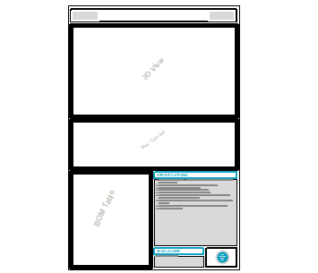
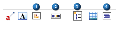
Use the following commands on the PMI tab→Template Layout group to add placeholders for dynamic content that is sourced from the model when the PDF is published. For examples showing how layout elements (1), (2), (3), and (4) appear when published, see Review a published 3D PDF.
-
To place each layout element, select the command, position the top-left corner of the object on the active sheet, and then click to place it.
-
To change the size of the container, click its border, and then click+drag a handle point.
| Command | Purpose | Notes | |
| | 3D View | Adds a container to display a 3D model. This container is populated when the document is published. | There can be multiple 3D Views per sheet, but just one View Carousel. |
|
| View Carousel | Adds a container for thumbnail preview images of all the model views. View carousels let reviewers browse through the available 3D model views in the output PDF. | Requires a 3D View container. One per sheet. |
|
| BOM Table | Adds a container for an interactive assembly BOM. The table and component data are populated when the document is published. | You can add a BOM Table without adding a 3D View. One per sheet. |
| | PDF Text | Adds an editable text area to the PDF for reviewers to add comments and notes in Adobe Acrobat Reader. | You can add multiple PDF Text containers per sheet. |


Each type of layout element has a thick border and is labeled with an identifying watermark.
Add text and other elements
You can use any of the commands on the Home tab in the Template Editor to draw, insert images, and add different types of text to the sheet. When you open an existing template, dynamic layout elements and static content (such as the title block, user-defined tables, and drawn elements) are shown. Placeholder text can be replaced before publishing. Associative text, such as property text, is replaced during publication based on its definition in the template. For examples, see Using property text and Using reference text.
When adding associative text, select From active document as the property text source. This extracts the property values from the model document during publication. For more information, see Property Text source list (Source: From Active Document).
Custom properties are defined in the model, not the template. To ensure custom property values are included in the published output, be sure to select the Add custom properties to PDF document option in the 3D PDF Publish dialog box.
-
Use the Rectangle command to represent a frame or border.
-
Use the Fill command to fill form areas with color.
-
Use the Image command to insert a bitmap image.
-
Add instructions using the Template Layout group→Text command
 . Use this command when you want to add plain text or associative text, a bullet or numbered list, superscript and fractions, color, vertical text, a border, word wrap, and other detailed formatting.
 -
Add associative information about model geometry in the 3D View window using the Template Layout group→Callout command
 . For example, to show size and depth of holes, slots, or threaded features, select an element in the 3D View window, and then specify the hole feature or other properties in the Callout Properties dialog box.
 -
Add tables with static content using the Template Layout group→Table command
 . You can add a table title, column headings, and type or paste information into the data cells. For more information, see User-defined tables.
After you place the table, you can:
-
Right-click and choose Properties to adjust its formatting.
-
Double-click a cell to edit its content.
-
© 2021 UDS