Bridge command
In the Subdivision Modeling environment, the Home tab→Modify group→Bridge command  connects the edges of selected cage elements by bridging the space between them with a lofted structure. You can define a curve to control the shape of the bridge.
Use the Bridge command to add feature-like modifications, such as handles or transitional features, or to create cutouts in the subdivision bodies being modified.
You can create a bridge that has two sides, as you would think of a typical structure that spans a river, or you can create a one-sided bridge that connects to your subdivision body and terminates in space.
For more information, see Connect cage faces or edges with a bridge.
Two-sided bridges
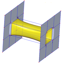
The following bridges have a start section and an end section that connect to different faces at both ends.
This bridge was defined between two cage bodies, by selecting one input face on each. The bridge was used to create a cutout on the connected cage bodies.
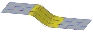
This bridge was defined by:
-
Two cage bodies,
-
Selecting three input edges at the start and at the end of the bridge,
-
Using linear or curved sketch elements to define the bridge path.
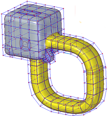
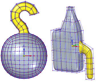
For this bridge, two input faces were selected at each end on the same body cage, and a sketch curve defines the bridge path.
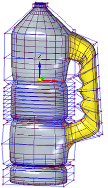
This thermos handle was defined by:
-
One cage body,
-
Selecting one input face at the start and one at the end of the bridge,
-
Using linear sketch elements to define the handle shape.
One-sided bridges
You can use a one-sided bridge to create the following type of lofted structure:
© 2021 UDS