Extrude command bar (ordered)
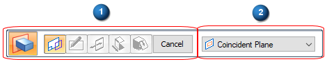
The Extrude command bar in the ordered environment guides you through the main steps (1) and step options (2), which change with each step and your selections:
- Main Steps
-
 Sketch Step
-
Specifies whether you construct the feature by drawing a new profile on a reference plane or by using an existing sketch. To construct the feature by drawing a new profile, on the Create-From Options list, select a reference plane option. To construct the feature using an existing sketch, select the Select From Sketch option.
If you choose the Select from Sketch option, you can click a sketch in the graphics window or from the list of sketches. If there is only one valid sketch, it is selected automatically.
 Draw Profile Step
-
Edits the profile for an existing feature. A profile is a 2D curve that defines the shape and location of the feature.
 Side Step
-
Defines the side of the sketch to which material should be added or from which material should be removed to construct the feature. The side step is not required when the sketch is closed.
 Extent Step
-
Defines the direction and depth of the feature or the distance to extend the sketch to construct the feature. The extent direction options are one direction only, two directions symmetrically, or two directions non-symmetrically. The extent depth options are: Through All, Through Next, From/To Extent, and Finite Extent.
 Treatment Step
-
Defines the draft and crowning options.
- Finish/Cancel
-
This button changes function as you move through the feature construction process. The Finish button constructs the feature using input provided in the other steps. The Cancel button discards any input and exits the command.
- Select Sketch Step Options
-
- Select
-
Sets the method of defining the feature.
-
Single—Select one or more individual sketch elements.
-
Chain—Select an endpoint-connected set of sketch elements by selecting one of the elements in the chain.
-
Face—Select a planar face or sketch region on the model.
-
- Accept
-
Accepts the selection. You can also right-click to accept the selection.
- Deselect
-
Clears the selection.
- Extent Step Options
-
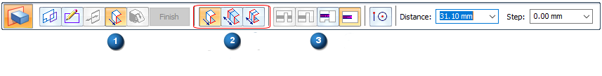
When the Extent Step is active (1), select the extent direction (2) and specify the extent depth (3):
- One-Sided Extent
-
Specifies that the feature extent is to be applied in one direction only.
- Non-Symmetric Extent
-
Specifies that the feature extent is to be applied non-symmetrically about the sketch plane. When you set the Non-Symmetric Extent option, Direction 1 and Direction 2 options are added to the command bar, so you can specify the extent options you want for each direction. For example, you can specify a Through All extent for Direction 1, and type a finite extent value of 20 millimeters for Direction 2.
- Symmetric Extent
-
Specifies that the feature extent is to be applied symmetrically about the sketch plane.
- Direction 1
-
Sets the extent options you want for Direction 1.
- Direction 2
-
Sets the extent options you want for Direction 2.
- Through All
-
Sets the feature extent so that the sketch is extruded through all faces of the part, starting at the sketch plane. You can extrude the sketch to either side of the sketch plane, or to both sides.
- Through Next
-
Sets the feature extent so that the sketch is extruded through only the next closed intersection with the part on the selected side. You can extrude the sketch to either side of the sketch plane, or to both sides.
- From/To Extent
-
Sets the feature extent so that the sketch is projected from the sketch plane to another specified surface. The From Extent is automatically set to the sketch plane. The To Surface can be any valid surface on the model.
To SurfaceSets the face to extend the feature to when the From/To Extent option is set.
Note:If the region is selected first, the From Extent surface can be redefined by dragging the extrude handle origin to another surface or plane. Click the extrude handle. Select the To Surface or plane. Right-click extrudes to the profile plane. A PMI dimension is automatically added for the extent length.
- Finite Extent
-
Sets the feature extent so that the sketch is projected a finite distance to either side of the sketch plane, or symmetrically to both sides of the sketch plane. Type the distance into the Distance box on the command bar.
- Keypoints
-
Sets the type of keypoint you can select to define a feature extent. You can define the feature extent using a keypoint on other existing geometry. The available keypoint options are specific to the command and workflow you use.

Sets the any keypoint option.

Sets the end point option.

Sets the midpoint option.

Sets the center point option. You can select the center point of an arc or circle.

Sets the tangency point option. You can select a tangent point on an analytic curved face such as a cylinder, sphere, torus, or cone.

Sets the silhouette point option.

Sets the edit point on a curve option.

Sets the no keypoint option.
- Distance
-
Specifies the distance to extend the feature when the Finite Extent option is set.
- Offset
-
Specifies the distance to offset the feature extent when the From/To extent option is set. For example, you can select a face as the From element and then specify that the feature extent is offset 10 millimeters.
- Step
-
Sets the distance value to increase or decrease in set increments when you move the cursor. For example, typing a step value of 10 millimeters and moving the cursor away from the sketch plane increments the distance from 10 millimeters to 20 millimeters, then to 30 millimeters and 40 millimeters.
- Treatment Step Options
-
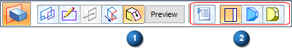
Lists the treatment options. You can specify No Treatment, Draft, or Crown.
- Treatment Options
-
Displays the Treatment Options dialog box.
- No Treatment
-
Specifies that you do not want drawn or crowning applied to the feature.
- Draft
-
Displays the draft options on the command bar so you can define the draft options you want.
- Crown
-
Opens a panel for you to define and apply the crown parameters to the feature.
- Crown Parameters
-
Displays the Crown Parameters dialog box.
- Angle 1
-
Sets the draft angle you want for the first extent direction.
- Flip 1
-
Flips the draft angle direction for the first extent direction. To see how the draft is applied, specify the draft angle you want, then move the cursor in the graphic window. If the draft angle is applied in the correct direction, click to construct the feature. If the draft angle is applied in the wrong direction, click the Treatment Step button, and then click the Flip button for the draft angle direction you want to change, then click to construct the feature.
- Angle 2
-
Sets the draft angle you want for the second extent direction. This option is available only when you have specified a symmetric extent.
- Flip 2
-
Flips the draft angle direction for the second extent direction. This option is available only when you have specified a symmetric extent.
© 2021 UDS