Activity: Modifying a part by moving select sets
Modifying a part by moving select sets
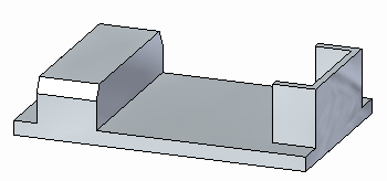
This activity demonstrates how to move multiple faces in a single operation. You will modify part (1) to the shape of part (2).
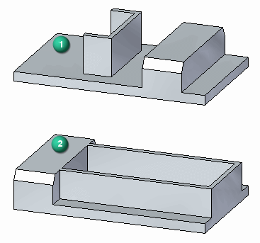
Click here to download the activity file.
Launch the Activity: Modifying a part by moving select sets.
If you are using Internet Explorer and a video is not displaying in your training guide, click the Tools tab (or gear icon)→Compatibility View settings, and then clear the selection of Display intranet sites in Compatibility View.
Open activity file
-
Open select_a.par.
Select feature to move
-
To select the feature to move, first select the face shown.
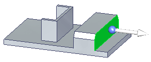
At this point, only the selected face moves.
-
Activate the Selection Manager mode.
-
Select the face shown.
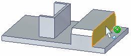
-
On the Selection Manager menu, choose Sets. This finds any sets that contain the selected face.
-
QuickPick displays the sets found. Click the Protrusion entry listed in QuickPick.
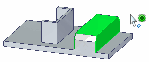
-
Press the Spacebar the exit the Selection Manager mode.
-
The selected protrusion feature participates in the move operation.
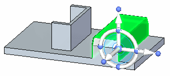
Move protrusion feature to other end of part.
Move the feature
-
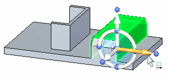
Click the axis on the steering wheel and move the feature to the other side of the channel-shaped feature.
-
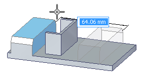
Move the feature to the approximate location and click. The move from point is the origin on the graphic handle.
-
Move complete. Press the Escape key to clear the select set.
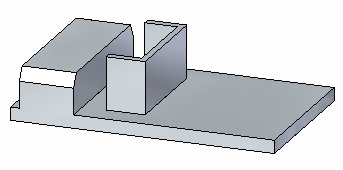
Select the channel-shaped feature
-
Activate the Selection Manager mode.
-
Select the face shown.
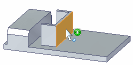
-
On the Selection Manager menu, choose Recognize→Rib/Boss.
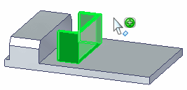
The Sets option would work here also.
-
Press Spacebar to exit the Selection Manager mode.
Move the channel-shaped feature
-
Click the axis on the steering wheel and move the select set to the edge of the part.
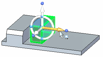
Use a keypoint on the edge of the part to define distance to move. Choose the keypoint option on command bar (1).
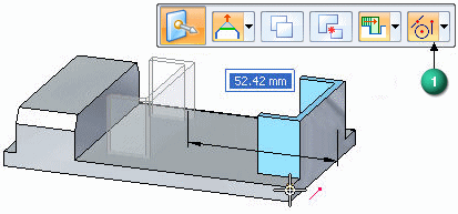
Extend the legs of the channel-shaped feature
-
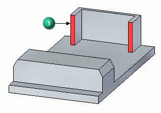
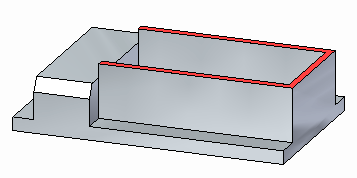
Select the face shown (1).
Note:Both red faces move together because they are coplanar. The Design Intent panel recognizes coplanar relationships and allows you to control the relationship between these faces.
-
Move the faces to the end of the protrusion feature as shown. Use a keypoint to define the distance.
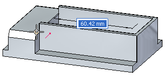
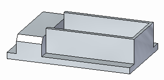
Move top face of channel-shaped feature
-
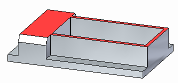
Select the top face.
-
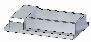
Move the top face to the top of the protrusion feature.
Move protrusion feature to end of part
-
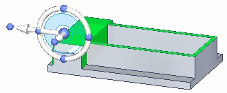
Select the protrusion feature.
Note:You can select the protrusion from PathFinder, QuickPick, or with Selection Manager. Make sure you select the protrusion shown.
-
Move the select set to end of part.
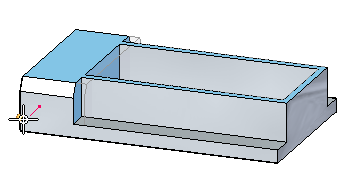
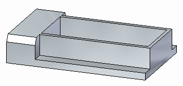
-
This ends the activity. Exit the file and do not save.
Summary
In this activity you learned how to create select sets for a move operation.
-
Click the Close button in the upper-right corner of the activity window.
© 2021 UDS