About the Path relationship
| In this section: 4.5.21.1. Using the Path command bar |
(Home tab→Assemble group→Path ![]() )
)
The Path relationship is used to define how one part will move relative to another part along a path. Like the Cam relationship, the path relationship requires a follower and a edge chain or edge as input (for more information, see About the Cam relationship). The center line of a slot feature can be used as input for the path relationship (for more information, see Slot command).
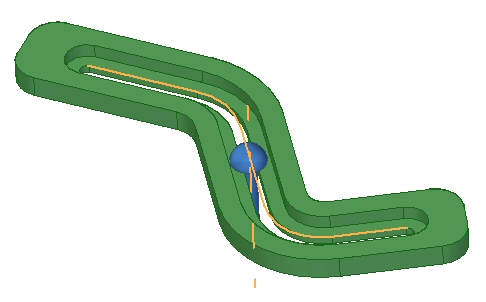
In the image shown above, two relationships keep the pin in the slot. A Mate relationship keeps the flat face of the pin in the recessed slot and the Path relationship intersects and aligns the cylindrical axis of the pin with the slot path. To have a valid slot path, the slot must have been created with the Slot command in the part environment (for more information, see Slot command).
The Path relationship can be used to define a range of motion for a component and can be used as an alternative to the range offset used when creating other relationships. Using the Path relationship for this purpose provides a more efficient processing method than using a range offset.
Limitations and Constraints
-
The edge chain can be defined from part geometry or sketch elements in included assembly sketches.
-
If the input chain is not tangent continuous, small fillets must be added to non-tangent corners when the path is defined for processing.
-
The edge chain does not have to be planar. 3D paths are also valid.
-
Open and closed chains are valid.
-
The chain can not intersect itself.
Use with motors
The Path relationship can be used to animate a part using a motor. For example, a Variable Table Motor can be used to move an assembly component, or a pattern of assembly components along a path by incrementing the variable associated with a fixed Path relationship.
© 2021 UDS