About the Cam relationship
| In this section: 4.5.19.1. Using the Cam command bar |
(Home tab→Assemble group→Path→Cam ![]() )
)
The Cam relationship is used to allow a Follower to maintain a tangential relationship with a transitional Cam surface. Two examples are shown next:
Tangent closed loop faces
The following image shows a Cam relationship between a closed loop of tangent faces on the Cam (A) and a single Follower (B).
The Follower face can be a plane, a cylinder, a sphere, or a point. However, when a planar face is selected as the follower element, the planar face is considered to be infinite. This means that in some cases this may not result in the desired behavior.
If part geometry changes such that the closed loop of tangent faces becomes non-tangent, the relationship fails.
Barrel Cam
In the second image, a barrel cam is created when a chain of curves are selected as input for the cam definition. The selected edges for the chain are merged into a composite curve for processing.
Shown next are the Follower (A) and the curve chain of the cam (B).
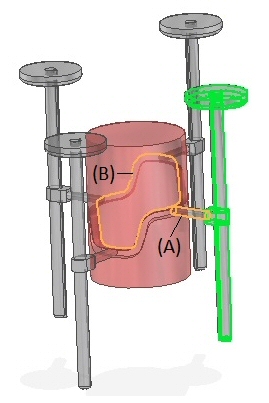
Supported cam geometry includes open and closed curves, a 3D path including arcs, and B-spline curves. The path must be tangent and continuous. The chain of curves can be from an edge coming from a sketch, design body, construction curve, or other similar input.
Supported Follower geometry includes cylinders, tori, spheres, points, or planes.
You can use the Flip command if the cam is positioned opposite the desired location.
Other relationships, such as axial align and mate, must be applied to maintain the desired orientation of the part containing the cam relationship during motor simulation.
Interference may exist at some positions and is ignored.
© 2021 UDS