Using connectors
About connectors
Connectors are a type of annotation that can be added to blocks and other 2D elements to create schematic diagrams, flow charts, and other drawings. An efficient way to use them is to create and arrange the blocks or other 2D objects on the drawing first, and then add the connectors using the Connector command.
You can also modify the appearance, location, and orientation of existing connectors by selecting a connector in the drawing and making changes on the Connector command bar and on the Connector Properties dialog box.
Connector shapes
There are five connector shape types: Line, Corner, Jump, Gap, and Step. Line and Corner connectors consist of start and end handles. Jump, Gap, and Step connectors also contain a midpoint handle that defines the center of the step or arc.
The midpoint of the jump arc or gap span can be connected to another line, such as a wire, or to another connector segment, so that it moves with the connected element.
The midpoint of the step can only be snapped to another object, not connected to it.
For more information about these shapes, see Connector command bar.
Adding connectors
The Connector command  initiates dynamic connector placement mode, in which a continuous series of connectors can be added to the drawing until you right-click, click the Select tool, or press the Esc key to exit.
Input to create a connector consists of two points. These two points can be on a block, another 2D graphic object, on a keypoint, on a grid, in free space, and even a point on another connector. The eligible points on a connector include a midpoint or start or end vertex.
Similarly, connectors can be connected to text, dimensions, leader lines, and other annotations. When you attach a jump connector to another element, both the jump and the connected element highlight to show they are connected. When the annotation moves, the connector moves with it.
Connector midpoints can be snapped to a grid during placement and editing.
Manipulating connectors
Once placed, connectors are driven by the objects they are attached to. If a connected block, element, or object is moved, the connector end point moves with it, stretching the connector line segment as needed to maintain connectivity.
For line and jump connectors only, if the other end of the connector is free, then the entire connector moves with the object.
You can easily align connectors using a grid and the Snap To Grid options on the Grid Options dialog box. You can snap to a point or to a line.
While modifying an existing connector, you can select a handle or the midpoint of a connector and drag it, and it will snap into position. When you turn off the grid, you turn off the snap-to-grid feature.
Highlight color
When you select a connector to edit, connector handles and connected elements are highlighted. It is helpful to know the default highlight color scheme, as it determines how connectors and connected elements will behave when you try to modify or move them.
-
The default selected connector color is magenta.
-
The default handle highlight color for the connector start point is light blue.
-
The default handle highlight color for the connector end point is gray.
-
The center point of a Jump, Gap, Step, and Corner connector is black.
The color scheme described above is the default color scheme. You may choose a different color scheme, which can be implemented through templates or a custom Connector style. See Connector style and properties to learn where these default colors are set and can be changed.
Changing connector shape and orientation
You can easily edit an existing connector.
You can change the shape of a selected connector by pressing S on the keyboard or clicking a different connector type in the Shape list on the command bar.
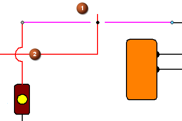
You might change a connector shape from a line to a jump where two wires cross in a diagram:
Line
Jump
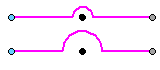
Or you can use a gap connector (1) instead of a jump connector (2).
You can change the default horizontal or vertical orientation of a jump, corner or step connector by pressing F on the keyboard or using the Flip button on the command bar.
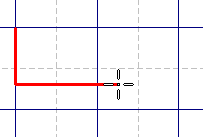
Corner connector before flip:
Corner connector after flip:
You can adjust the jump radius of a jump connector by typing a new value in the Jump radius/gap box on the command bar and pressing Tab to update the connector.
You also can adjust the position of the jump by selecting the middle handle and moving it along the connector segment.
Only one jump per connector is allowed. However, you can create a string of connectors with one jump each, which behaves like a single connector with multiple jumps.
Set the start and end terminators of the connectors in the middle to the Blank option. Do the same for the end terminator of the first connector and the start terminator of the end connector.
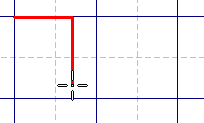
You can create a U-shaped connector by placing a step-type connector, then selecting the connector middle handle and dragging it.

Cut, copy, or paste a connector
You can cut, copy, and paste a selected connector using those commands on its shortcut menu. Press the Ctrl key while you drag the connector to both copy and move the connector.
Rotate, mirror, scale, or move a connector
Connector annotations can be rotated, mirrored, scaled, and moved using those commands. If you use these commands on a connected object, the connector segment will change with it. If you select the connector segment itself, only the connector will change.
To move an individual connector, it is more efficient to move the connected object. You cannot fence select connectors to move them.
Disconnecting a connector
To disconnect a connector from an object, select and drag the connector handle off the object.
© 2021 UDS