Activity: Placing tubes in assembly with XpresRoute
Activity: Placing tubes in assembly with XpresRoute
When you complete this activity, you will be able to:
-
Add tubes to the design using PathXpres.
-
Add tubes by manually creating tube paths.
-
Add end treatments to tubes.
-
Modify tube paths and update the tube part.
-
Edit the tube part after the tube is created.
-
Output a Bend Table of the tube parts for manufacturing.
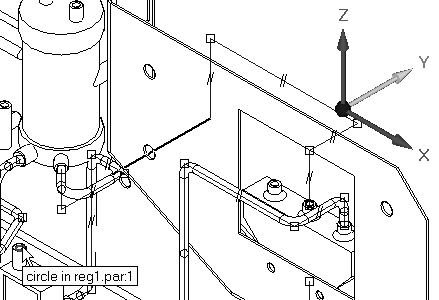
Click here to download the activity file.
Launch the Activity: Placing tubes in assembly with XpresRoute.
Use PathXpres to automatically route the first tube path
-
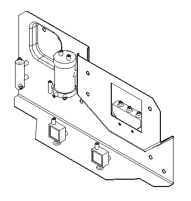
Open Xpres.asm with all the parts active.
-
Click Tools→Evirons→XpresRoute.

-
Choose Application menu
 →Settings→Options→Tube Properties tab.
 -
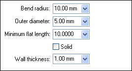
Set the tube properties values as shown, and then click OK.
-
Click the PathXpres command.

-
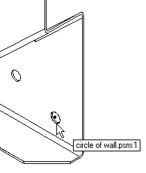
For the first port, on the part wall.psm, click the front edge of the far right hole.
 Note:
Note:The front edge is selected so the tube will extend toward the front of the assembly. If you select the rear edge of the hole, the tube path tries to project toward the rear of the assembly.
-
For the second port, select the rear inlet on the blue part reg1.par as shown. After you click the rear port, the tube path should highlight.
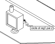
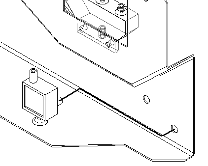
-
Accept the tube path by clicking Finish. The tube path changes to the profile color and displays the relationships applied along the path.

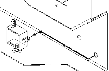
-
Click Cancel.
Place the tube on the tube path
-
Click Home→Tubing→Tube
 . Note:
The Tube Options dialog box should display as shown. If the dialog box is not displayed automatically, click the Tube Options button. Check the values against the values in the image below and make any necessary adjustments.
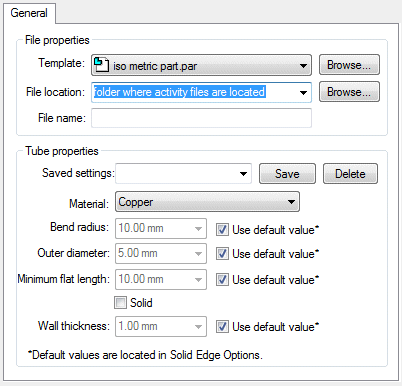
-
To select the folder where the part file for this tube will be stored, click the Browse button and select the folder location where the activity files are located.
-
On the dialog box, clear the Show this dialog when the command begins option. To see this box in the future, click the Tube options button on the command bar.
-
Type tube001 as the new file name and click OK.
-
Select the tube path just created.
-
In the Name box, tube001 is displayed. Click the Accept button.
The result should look like the following illustration.
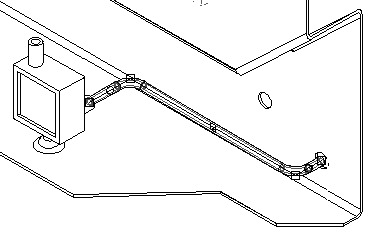
-
To accept this result, click Finish.

-
Click Cancel.
Create a new path and a new tube
-
To construct a second path, click PathXpres.

-
For the first port of this new path, click the hole to the left of the first hole selected on wall.psm.
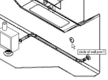
-
For the second port, click the bottom port on the valve body pvalve.par.
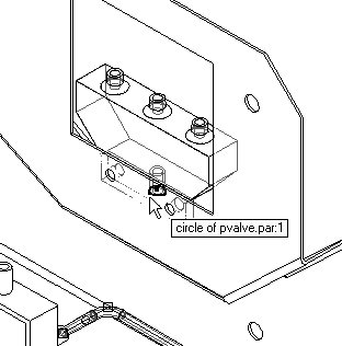
-
To accept this tube path, click Finish on the command bar.
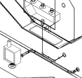
-
To place a tube using this path, click the Tube command.

-
Select the path just created.
-
In the name box, type the name tube002.
-
Click Preview.
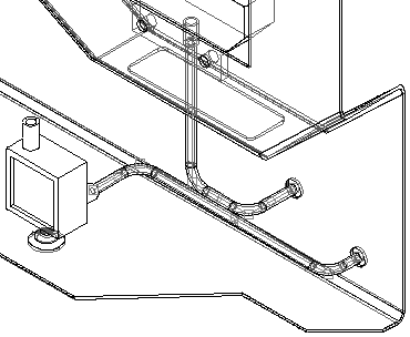 Note:
Note:In the 3D window, it looks like the two tubes intersect each other. By checking the window with the right view of the assembly, you can see that the two tubes do not interfere with each other.
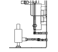
-
Click Finish to complete the placement of the tube part.
-
Click Cancel.
Create another new path and tube
-
Click PathXpres.

-
Select the far right port on pvalve.par as shown.
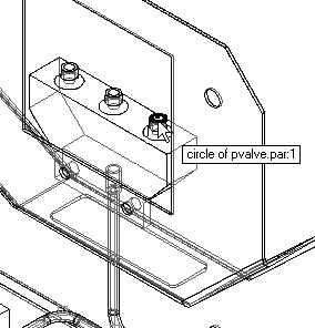
-
Select the top port on the blue reg1.par as shown.
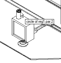
-
The resulting path should look like the following illustration.
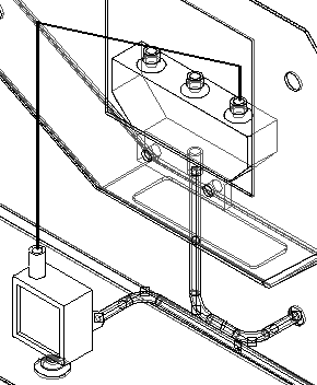
-
To see another path option, on the command bar, click the right blue arrow once. Keep clicking the blue arrow until the path looks like the illustration below. If you click too many times, use the left blue arrow to cycle back through the options.
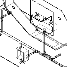
-
Click Finish to accept this path.
-
To construct a tube part from this path, click the Tube command.

-
Select the path just created, type tube003 for the tube part name, and click Preview to view the part. The result should look like the following illustration.
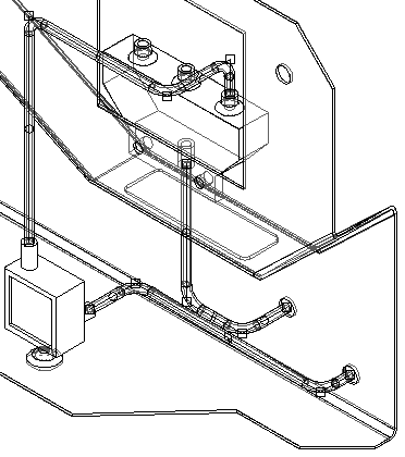
-
Click Finish.
-
Click Cancel.
Create a new path, then move a segment to maintain a clearance
-
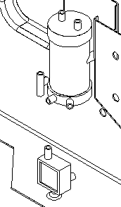
The fourth path will be created in the middle of the assembly. Adjust the view as shown.
-
Click PathXpres and construct a tube path from the bottom right port of the tank2.par to the rear port of the green reg1.par. Do not click finish.
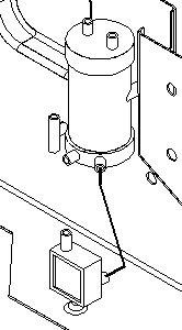
-
Cycle through the tube path solution options to get a tube path as shown by clicking the right blue arrow on the command bar.
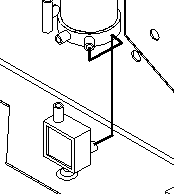
-
Click Finish.
-
Zoom the area on the top portion of the tube path as shown.
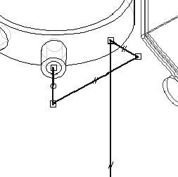
-
Click Home→Segments→Move Segment
 .
. -
Hold down the left mouse button over the second segment in the path, and drag the path segment to the right. Use additional windows to make sure you do not cause an interference with the other parts in the assembly.
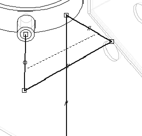
-
Using this modified path, construct a tube part named tube004. Click the Tube command, and select this path.
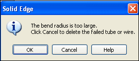
Depending on the new segment position, the software may display a warning dialog box stating that one of the segments has violated either the minimum flat length or the bend radius as specified in the options settings. This is not an error message but a notification that this tube does not meet the requirements as specified in the Tube Options dialog box. Take the time to study whether or not the tube path is still valid, and modify the tube path accordingly. The tube part will not be placed into the assembly if you click OK.
-
If this warning is displayed, click OK to dismiss the dialog box.
-
Click the Move Segment button.

-
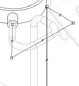
Select the tall vertical segment, and drag it towards the rear of the assembly.
-
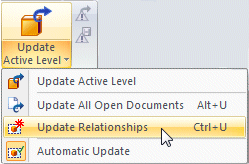
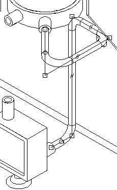
To force the tube part to reflect the new tube path, click Tools→Update group→Update Active Level list→Update Relationships. Notice that the tube recalculates and now resides on the newly modified path.
-
To construct and modify another tube path, click PathXpres.

-
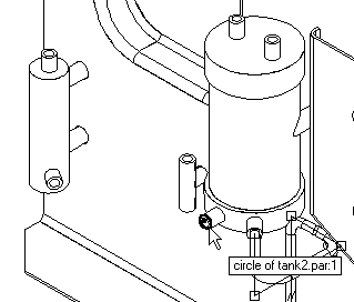
For the first port, select the remaining bottom tube port on tank2.par.
-
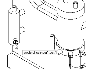
For the second port, select the bottom port on cylinder1.par.
-
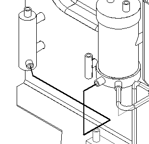
Cycle through the path options until a path is found that resembles the path as shown.
-
Click Finish.
Modify the tube path and add end treatments
-
Click the Select tool.

-
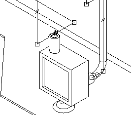
As shown, select the parallel relationship on the line segment.
-
Press the Delete key to delete it.
-
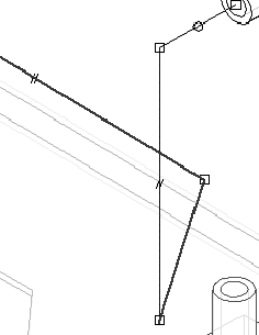
Click the Move Segment button.

-
Select the endpoint of this line segment closest to the rear of the part, and drag it to the left to make it longer.
-
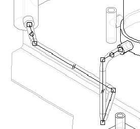
Click the Tube button and construct a tube part named tube005 from this modified path.
-
If the Tube Options dialog box is shown, click cancel.
-
Once tube005 has been placed, click the Select tool and select tube005.par. Double-click tube005.par in PathFinder to edit the definition, and then edit the tube by clicking the End Treatment step.

-
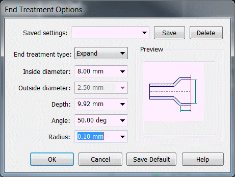
Increase the extent of End 1 by typing 9.92 mm.

-
Click End Treatment Options for end 1, and edit as shown in the illustration. Then click OK on the End Treatment Options dialog box.

-
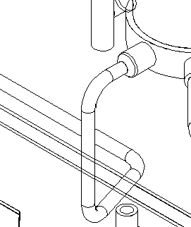
Click Preview, and then click Finish. The end of tube005 is shown.
-
If the Tube Options dialog box is shown, click Cancel.
Use OrientXpres to manually route a tube path and place a tube
-
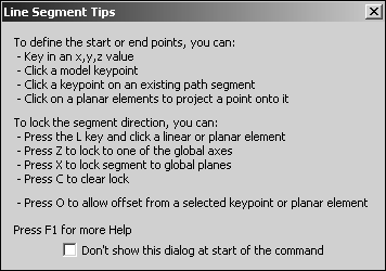
Click Home→Segments→Line Segment
 .
. Cancel the Line Segment Tips box shown if it displays.
-
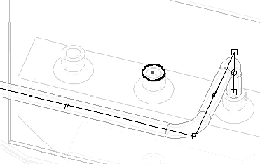
As the starting point for the new path, select the middle port on pvalve.par. Adjust the view angle to get a better view.
-
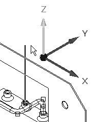
To lock this line segment to this axis, select the vertical axis on OrientXpres.
 Note:
Note:To move the OrientXpres triad to another screen location, click and drag the triad by the origin.
-
Extend this vertical line 40 mm and then click.
-
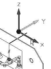
Click the axis as shown, and extend the line 40 mm toward the rear of the part and then click.
-
Extend the next line segment the distance to the center of the hole in wall.par. Do this by selecting the axis shown and then positioning the cursor over the hole feature. When the center of the hole feature highlights, left-click. The line will extend to that distance horizontally.
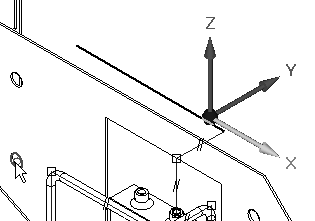
-
Select the axis and extend the line down to the hole’s center as in the previous step. Highlight the center, and accept this as the distance.
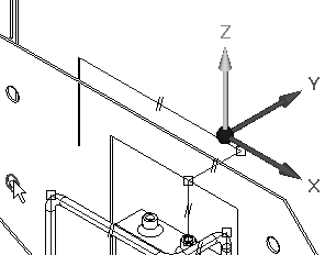
-
Select the axis shown in the illustration, and extend the line to the center of the top port on green reg1.par.

-
Select the axis as shown, and extend the line to the port center.
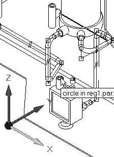
-
Select the axis as shown, and extend the line to the port center.
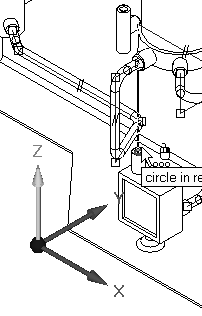
-
To end the line segment command, right-click. The path is now complete.
-
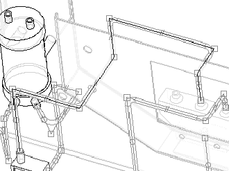
From this path, construct a tube part named tube006.
-
If the Tube Options dialog box is shown, click Cancel.
Place a tube path manually
-
To construct a second path manually, on the XpresRoute toolbar click the Line Segment button.

-
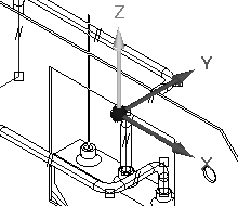
Select the remaining port on pvalve.par as the starting port. Lock the OrientXpres into the vertical axis as shown.
-
Extend this line segment by 50 mm and click.
-
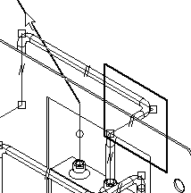
Lock the next line segment to the plane as shown (click the plane with the mouse when it highlights), and extend the line 100 mm towards tank2.par. Use the other views to determine a reasonable height for the line segment. Right-click to restart the line command.
Note:Locking to the plane allows construction of an angled tube segment.
-
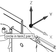
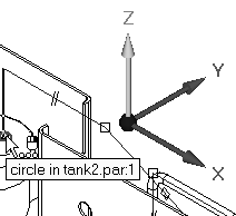
Start the next line segment at the end of the previous line segment. Lock the next segment as shown, and extend it to one of the port centers on tank2.par.
-
Extend the final line segment to the port center by locking the line to the vertical axis.
-
Right-click to exit the Line Segment command.
-
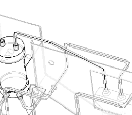
From this tube path, construct a tube part named tube007.
-
If the Tube Options dialog box is shown, click Cancel.
-
Click the select tool. In the assembly window, right-click. On the shortcut menu, click Show/Hide All Component. Turn on the display of center lines.
 Note:
Note:The center lines shown can shown on for individual tubes, rather than all, can be dimensioned too, and can be placed on a drawing sheets in the draft environment.
-
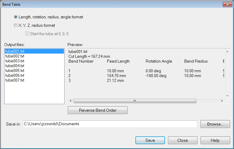
Click Tools→Assistants→Bend Table.

-
Click the Select All Tubes button and accept. All the tubes in the assembly should highlight.
The bend information for the highlight tube part displays in the right portion of the dialog box. To view other tube part information, highlight the tube part file on the left portion of the dialog box.
-
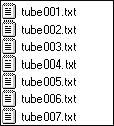
Click Save. QY CAD will construct .txt files for each tube part in the folder specified in the Bend Table dialog box.
-
Save and close this file. This completes the activity. However, if time permits, use the remaining ports to practice constructing additional tubes in the assembly.
-
Click the Close button in the upper - right corner of this activity window.
Lesson summary
In this lesson you learned how create tube paths both automatically and manually using OrientXpres. Once created, the tube paths were edited and tubes placed on the different paths. A bend table was created for the tube paths created.
-
The XpresRoute provides the basic tools for creating tubes for fluid and air transfer. Other tube part features can be modeled by in-place activating to the part environment.
-
XpresRoute provides editing, modification, and output tools for creating and manufacturing these types of tube parts.
-
PathXpres is an automated method of generating a 3D tube path between two ports. Solid Edge calculates as many solutions as possible for connecting the two ports, where the solution solves a maximum of five (5) segments.
-
OrientXpres activates automatically when you click the line segment command. This tool allows PathXpres to lock the line segment direction or planar orientation along a specific vector regardless of the mouse position on the screen. OrientXpres is activated by default, but its options are not active.
-
The Tube command is used to construct a tube part file from a tube path. The tube path must exist before the tube part can be constructed. When the tube command is clicked, the command bar updates to show the options and steps required for tube part creation.
-
The Bend Table command is accessed on the Tools tab. Bend table allows the extraction of tube information to an ASCII text file for use on the shop floor.
Lesson review
Answer the following questions:
-
What is the difference between PathXpres and OrientXpres?
-
What defines a tube?
-
If a path segment is moved, does the tube change to reflect the new position of the path segment?
-
After deleting a tube part, can the tube name be reused?
-
What information is contained in a bend table?
Answers
-
What is the difference between PathXpres and OrientXpress?
PathXpres finds as many valid solutions for routing between two points. You can view each solution and choose the one you desire.
OrientXpres allows you to route the path manually. Tools exist in path express to lock the direction of the path segments to either planes or axes.
-
What defines a tube?
A tube is defined by a path which routes the tube, and a part file which contains the geometry of the tube. The part file shows up as a part in the assembly pathfinder.
-
If a path segment is moved, does the tube change to reflect the new position of the path segment?
Paths are associatively linked to the tube part. Changes in the path cause the tube to change. The Tools>update all relationships command will refresh the tube geometry.
-
After deleting a tube part, can the tube name be reused?
A tube name can be assigned to another path if the tube part file is first deleted. If not, when creating the new tube, a message showing the part file exists will display.
-
What information is contained in a bend table?
The bend table contains the information needed to manufacture the tube. Segment properties such as length, rotation, radius, and angle format is contained in the bend table. Bend tables can also be formatted for X,Y, and Z radius format.
© 2021 UDS