Activity: Creating a wire harness with Electrical Routing
Activity: Creating a wire harness with Electrical Routing
This activity guides you through the creation of a harness design that contains several wires, a cable, and a bundle.
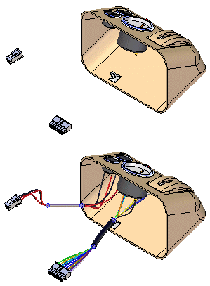
Click here to download the activity file.
Launch the Activity: Creating a wire harness with Electrical Routing.
Open activity file
-
Open the assembly harness.asm.
Open the Electrical Routing environment
![]()
-
Click Tools tab→Environs group→Electrical Routing.
The system displays the Electrical Routing environment. The ribbon contains the commands you use to create wire harness conductors (wires, cables, or bundles).
You will use PathFinder for most of this activity.
Activate the parts in the assembly
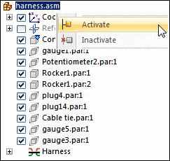
This activity requires that the parts in the assembly are active. Several factors determine whether or not all parts within the assembly are active on your computer.
-
To ensure that the parts are active, in PathFinder, right-click the harness.asm entry, and click Activate on the shortcut menu.
Hide the console part
![]()
-
In PathFinder, position the cursor over the Console1.par entry, and then right-click to display the shortcut menu.
-
On the shortcut menu, click Hide to hide the console part.
Start the HarnessWizard
![]()
The Harness Wizard consists of three dialog boxes that create a harness design automatically based on information contained in an imported net list file.
-
On the ribbon, click Home tab→Wizard group→Harness Wizard
 .
.
Specify information for Harness Wizard Step - 1 of 3
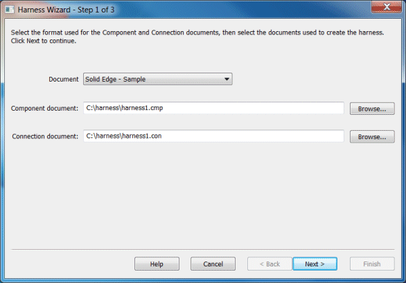
The Harness Wizard - Step 1 of 3 dialog box specifies:
-
The format for the eCAD net list file.
-
The component document used to create the harness.
-
The conductor document used to create the harness.
-
From the Document list, select QY CAD – Sample.
-
In the Component document box, use the Browse button to select harness1.cmp in the folder containing the activity files.
-
In the Connection document box,use the Browse button to select harness1.con in the folder containing the activity files.
-
Click the Next button.
-
If a warning dialog box appears, click the Accept Warnings button.
Specify information for Harness Wizard Step - 2 of 3
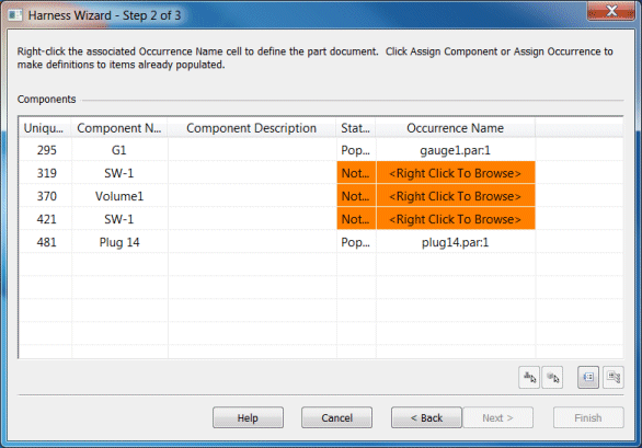
The Harness Wizard - Step 2 of 3 dialog box displays information about the components used to create the wire harness. The dialog box contains commands and options that allow you to:
-
Assign components.
-
Assign occurrences.
-
Populate components.
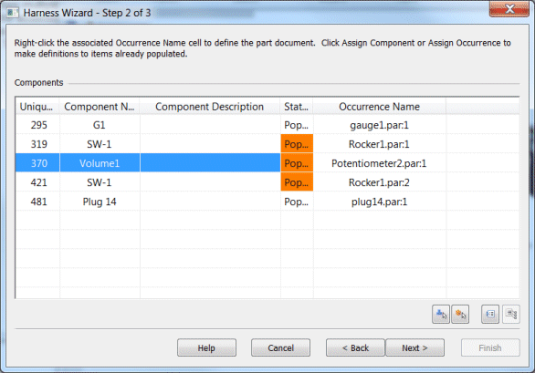
Notice that the status for component Volume1 is Not Populated. This indicates that the component has not been assigned to a part. Normally, you would use the Assign Terminals command to assign components and terminals before running the wizard. However, if this has not been done, you can make these assignments within the wizard.
Also notice that there are multiple instances of component SW-1. You will use the Assign Occurrence command to ensure these instances are mapped to the appropriate .cmp file entry, you
-
Right click the row containing the Unique ID value of 319 for SW-1 and click Assign Occurrence.
-
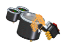
In the graphics window, click Rocker1.par:1, as shown in the illustration.

-
Right click the row containing the Unique ID value of 421 for SW-1 and click Assign Occurrence.
-
In the graphics window, click Rocker1.par:2, as shown in the illustration.
-
Right click the row containing Volume1 and click Assign Component.
-
In the graphics window, click Potentiometer2.par, as shown in the illustration.

-
Notice that the dialog box updates to indicate the status of the components is now populated
-
Click the Next button.
Specify information for Harness Wizard Step - 3 of 3
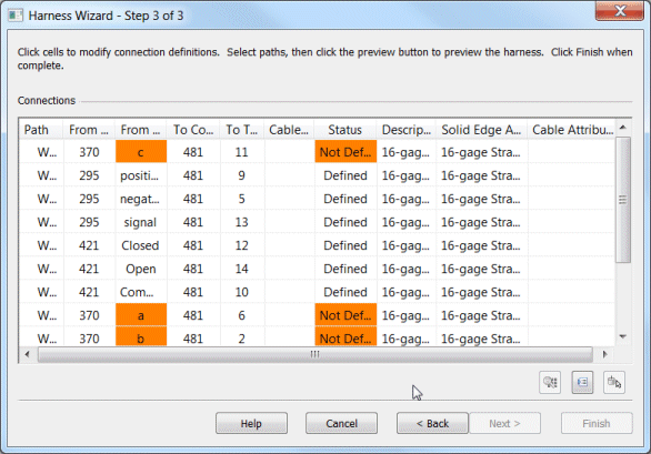
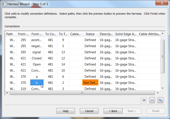
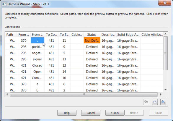
The Harness Wizard - Step 3 of 3 dialog box displays information about the conductors used to create the wire harness. The dialog box contains commands that allow you to:
-
Assign terminals.
-
Delete wires from the harness.
-
Assign attributes to a wire or cable.
-
Preview the harness.
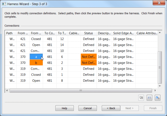
Notice that there are three From Terminals highlighted in orange and the status for these terminals is Not Defined. These represent terminals on the Volume1 component that need to be defined.
Assign terminal A
-
Right-click From Terminal a and click Assign Terminal.
-
On the status bar at the bottom of the window, click the Zoom Area button
 .
. -
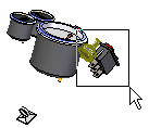
Click above and to the left of Potetionmeter2.par, and then again below and to the right as shown in the illustration. This defines a rectangle that becomes the view area.
-
Right-click to end the Zoom Area command.
-
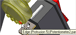
Click the circular edge to assign terminal a.
Assign terminal B
-
Right-click From Terminal b and click Assign Terminal.
-
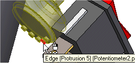
Click the circular edge to assign the terminal.
Assign terminal C
-
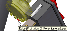
Right click From Terminal c and click Assign Terminal.
-
Click the circular edge to assign the terminal.
-
Click Finish to complete the wizard.
Fit the view
![]()
-
Click the View tab→Orient Group→Fit command to fit the assembly in the window.
View PathFinder
-
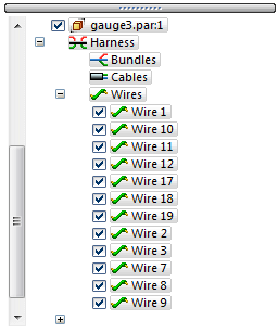
In PathFinder, click the + symbol adjacent to the Wires entry.
Notice entries have been added for every wire created with the Harness Wizard.
Create a bundle
![]()
The Bundle command creates a harness bundle from a set of wires and cables. The result is a single path that can be created across several components within the harness assembly. When defining the path, you can define points to create the path or you can select an existing path created with the Path command. For this bundle, a path has already been created.
-
In PathFinder, click the arrow next to the Paths entry.
-
Right-click Path_1 and click Show on the shortcut menu.
-
Click the Home tab→Electrical Routing group→Bundle command
 .
. -
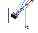
Drag a box around plug14.par, as shown in the illustration, to select the wires to include in the bundle.
-
Click the Accept button.
-
Select the Use Existing Path button
 on the command bar.
 -
Click the existing path shown in the illustration.

-
Click the Accept button.
-
Click Preview and then click Finish.
Re-select the Harness Wizard command
![]()
You need to use the Harness Wizard to place another set of wires in the assembly.
-
Click the Home tab→Wizard group→Harness Wizard button
 .
. -
In the Harness Wizard - Step 1 of 3 dialog box:
-
From the Document list, select QY CAD — Sample.
-
In the Component document box, use the Browse button to select harness2.cmp.
-
In the Connection document box, use the Browse button to select harness2.con.
-
Click the Next button.
-
In the Harness Wizard - Step 2 of 3 dialog box, click the Next button.
-
In the Harness Wizard - Step 3 of 3 dialog box, click the Finish button.
Change the assembly display
![]()
-
On the status bar at the bottom of the window, click the Visible and Hidden Edges button
 .
.
Zoom in on the assembly
![]()
-
On the status bar at the bottom of the window, click the Zoom Area button
 .
. -
Drag a box around plug4.par, as shown in the illustration. This defines a rectangle that becomes the view area.
-
Right-click to end the Zoom Area command.
Create a wire
![]()
-
Click the Home tab→Electrical Routing group→Wire command
 .
.
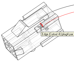
Select the first point for the wire
-
Make sure the Create Path button is selected
 .
. -
Click the Locate Filter button
 .
. -
From the list of keypoints, select the Center Point button
 .
. -
Locate the center point shown in the illustration, and when it highlights, click to select it.
Fit the view
![]()
-
Click View tab→Orient Group→Fit to fit the assembly in the window.
Zoom in on the upper gauge
![]()
-
Use the Zoom Area command
 to zoom in on the area shown.
 -
Right-click to end the Zoom Area command.
Select the end point for the wire
![]()
-
Locate the center point shown in the illustration, and when it highlights, click to select it.
-
Position the cursor above and beyond the terminal as shown in the illustration, and right-click to accept the end point.
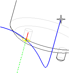
-
Set the Material as shown in the illustration.

-
Click the Preview button.
Finish the wire
![]()
-
Click the Finish button to complete the wire.
Fit the view
![]()
-
Click View tab→Orient Group→Fit to fit the assembly in the window.
Zoom in on the assembly
![]()
-
Select the Zoom Area command
 .
. -
Zoom in on plug4.par. Right-click to end the command.
Create another wire
![]()
-
Click Home tab→Electrical Routing group→Wire
 .
. -
Use the same options you used to create the first wire.
-
Select the circular edge shown in the illustration to define the first point for the wire.
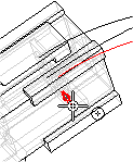
-
Select the circular edge shown in the illustration to define the end point for the wire.
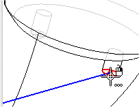
-
Position the wire as shown in the illustration and click the Accept button.

-
Set the Material as shown in the illustration.

-
Click the Preview button.
Finish the wire
![]()
-
Click the Finish button to complete the wire.
Fit the view
![]()
-
Click View tab→Orient Group→Fit to fit the assembly in the window.
Create a cable
![]()
-
Click the Home tab→Electrical Routing group→Cable command
 .
. -
Drag a box around plug4.par, as shown in the illustration, to select the wires to include in the cable.

-
Click the Accept button.
-
Make sure the Create Path button is selected
 .
. -
Create the path as shown in the illustration.

-
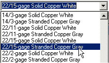
Set the Material to 22/15-gage Stranded Copper Gray as shown in the illustration.
-
Click Preview and then click Finish.
Shade the view
![]()
-
On the status bar at the bottom of the window, click Shade with Visible Edges
 .
.
Create a solid body of the wire harness
![]()
-
Click the Home tab→Select group→Select Tool button
 .
. -
In PathFinder, right-click the Harness entry to display the shortcut menu.
-
On the shortcut menu, click Create Physical Conductor.
The system processes for a few seconds, then solid bodies are created for the harness conductors.
Change the view orientation
![]()
-
Press Ctrl+R to align the view with the Right view.
Zoom in on the assembly
![]()
-
Use the Zoom Area command
 to zoom in on rocker1.par, as shown in the illustration.
Move a wire
![]()
-
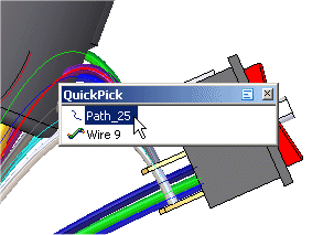
Position the cursor over the path shown highlighted in the illustration above, stop moving the mouse for a moment, and notice that the cursor image changes to indicate that multiple selections are available. Also notice that the cursor image indicates which button you must click to display the QuickPick list. In this case, the right mouse button
 .
. -
Click the right mouse button, and the QuickPick list is displayed. Move the cursor over the different entries in QuickPick, and notice that different elements of the model highlight. QuickPick allows you to select exactly the element you want, the first time, without having to reject unwanted elements.
-
Use QuickPick to highlight the path used to define Wire 9 and then click the right mouse button.. In this example, it is Path_25, but your path may have a different name. If multiple paths are displayed in QuickPick, select the path closest to the occurrence in Rocker1.par.
-
On the shortcut menu, click Edit Definition.
-
On the command bar, click the Select Points Step.
-
Click the point shown in the illustration.

-
Drag the point to the approximate location shown in the illustration, and then right-click to place the wire.

-
Click Finish to complete the command.
Move two more wires
![]()
-
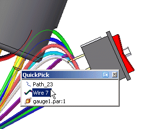
Use the method described in the previous step to move the path used to define wire 7.
-
and the path used to define wire 8.
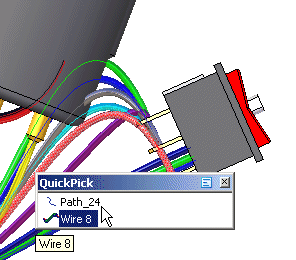
After you have moved these wires, the wire harness should look similar to the illustration above.
Fit the view
![]()
-
Click View tab→Orient Group→Fit to fit the assembly in the window.
Change the view orientation
![]()
-
Press Ctrl+I to align the view with the Isometric view.
Display a hidden part
![]()
-
In PathFinder, right-click the Console1.par entry, and then click Show. This displays the hidden part.
Hide the wires in the harness
![]()
-
In PathFinder, right-click the Wires entry, and then click Hide to hide the wires.
Create a Wire Harness Report
![]()
You can create a report that lists the components and connections contained in an assembly.
-
Click Tools tab→Assistants group→Harness Reports.
-
In the Harness Report dialog box:
-
Select the Connections option.
-
Select All harness connections in the assembly.
-
Click OK to generate the report.
A report dialog box displays a list of cables expanded into an indented list of the wire paths.
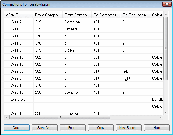
You can generate a report based on all components or connections in the assembly, the components or connections that are currently shown in the assembly, or the components or connections that are currently selected in the assembly. You can save reports, print reports, and copy reports to the clipboard.
-
Click the Close button to dismiss the report.
-
Return to the Assembly environment
![]()
-
Click the Tools tab→Close group→Close Electrical Routing button
 .
.
Save the file
![]()
-
On the Quick Access toolbar, click the Save button to save the document
 .
.
Activity complete. Try modifying the wires using the Properties dialog box.
© 2021 UDS