Path command bar
- Main Steps
- Select Points step
-
Defines the points used to create the path.
- End Conditions step
-
Specifies the end conditions for the path.
- Curve Length step
-
Specifies the end conditions for the path.
- Preview/Finish/Cancel
-
This button changes function as you move through the feature construction process. The Preview button shows what the constructed feature will look like, based on the input provided in the other steps. The Finish button constructs the feature. After previewing or finishing the feature, you can edit it by re-selecting the appropriate step on the command bar. The Cancel button discards all input and exits the command.
- Show Connector Information
-
Displays the component and terminal names for the selected conductor.
- Redefine Point
-
Redefines the location of an existing point you select. You can use the Relative/Absolute option on the command bar to redefine its position relative to its current position or with respect to its absolute position in the document. You can type a new coordinate in the X, Y, or Z boxes, select a keypoint, or click a point in space.
- Assigned Terminals
-
Changes the filter to locate any center point or cylindrical face or locate only the center points and cylindrical faces of assigned terminals. This is helpful when there are many terminals in a conductor and you want to select the terminals that are assigned.
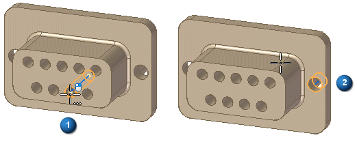
For example, with the option deselected, you can locate both the center point (1) and the cylindrical face (2).

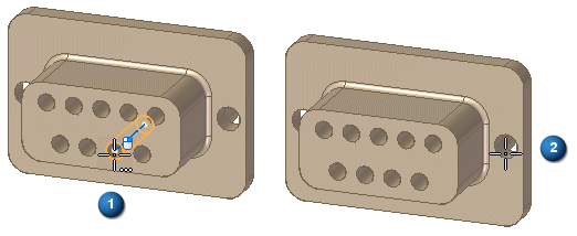
If you select the option, you can locate a center point (1) because it has an assigned terminal. However, you cannot select a cylindrical face (2) because it has no assigned terminal.

- Locate Filter
-
Sets the type of keypoint on existing geometry to define the path.

Locates cylindrical faces for path to pass through.

Locates the center or end point.

Locates any keypoint.

Locates an end point.

Locates the center point of a circle, arc, square, or rectangle.

Locates a midpoint.

Locates a silhouette point.

Locates an edit point.

Locates an x,y,z point in free space.

Turns off keypoint location.
- Flip
-
Reverses the path direction between cylinder ends.

You can flip the path direction while creating or editing the path.
- Relative/Absolute Position
-
Specifies whether the value you type is relative to the current point position or is based on the global origin of the document. The global origin is the point where the three default reference planes intersect (the exact center of the design space).
- X
-
Sets the position for the x axis.
- Y
-
Sets the position for the y axis.
- Z
-
Sets the position for the z axis.
- Deselect (x)
-
Clears the selection.
- Accept (check mark)
-
Accepts the selection.
- End Conditions options
-
- Show/HIde Tangency Control Handles
-
Specifies the end condition for the start of the curve. You can specify whether or not the start point of the curve is tangent to an element you select, and the length of the tangent vector. You can define the length of the tangent vector by dragging the tangent vector handle using the mouse or you can type a value.
- Start
-
Specifies the end condition for the start of the curve. You can specify whether or not the start point of the curve is tangent to an element you select, and the length of the tangent vector. You can define the length of the tangent vector by dragging the tangent vector handle using the mouse or you can type a value.
- End
-
Specifies the end condition for the finish of the curve. You can specify whether or not the start point of the curve is tangent to an element you select, and the length of the tangent vector. You can define the length of the tangent vector by dragging the tangent vector handle using the mouse or you can type a value.
- Curve Length step options
-
- Fixed Length
-
Specifies whether of not the path is a fixed length or not. If you select this option, the Length value field becomes active and you can enter a fixed length for the curve.
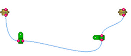
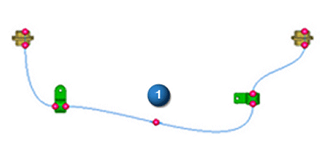
When setting the fixed length of a curve with no free edit points,

a free edit point is added at the midpoint (1) of the longest segment between edit points on the curve.

- Constraint Direction
-
Specifies the constraint direction in which the control points move when you increase or decrease the curve length.
- Length
-
Specifies the length for a fixed length curve.
- Other command bar options
- Name
-
Displays the feature name. Feature names are assigned automatically. You can edit the name by typing a new name in the box on the command bar or by selecting the feature and using the Rename command on the shortcut menu.
© 2021 UDS