Fillet Weld Options dialog box
The user interface in this dialog box is determined by the active Weld Symbols standard. You set the Weld Symbols standard on the Drawing Standards tab in the QY CAD Options dialog box. The two standards that are available are ANSI/ISO/DIN or GOST.
- Saved Settings
-
Lists the saved settings. You can select the arrow to recall a previously saved setting. Saved settings are saved to special text files located in the QY CAD/Template/Reports folder.
- Save
-
Saves the current weld symbol parameters to a name you define. You can recall the saved setting to place it more quickly later.
- Delete
-
Deletes the selected saved setting.
- Preview
-
As you define a weld symbol, the Preview pane shows how it will appear when placed on the model.
Example: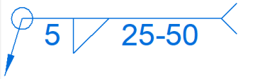
ANSI/ISO/DIN weld symbol properties
To learn how to build a simple weld symbol, see Example: Define a weld symbol.
- Field/Site Symbol
-
Specifies a flag points right symbol, a flag points left symbol, or none.
- All Around Symbol
-
Specifies the all around symbol or none.
- Weld Symbol
-
When selected, displays a list of weld type symbols. After selecting the type of weld symbol from the Weld Symbol list, you can use the other weld symbol definition options to define the content and layout of the weld symbol.
- Identification Line Symbol
-
Specifies an identification line above, identification line below, or none.
- Intermittent Symbol
-
Specifies the intermittent symbol or none.
- Tail Symbol
-
Specifies an open tail, a closed tail, or no tail. Use the Tail Note 1 and Tail Note 2 boxes to define the content.
- Number of
-
For ANSI/ISO/DIN weld symbols, assigns a weld number operation to the current set of weld options.
- Add New Operation
-
For ANSI/ISO/DIN weld symbols, clears all boxes and increments the operation number.
- Operation
-
For ANSI/ISO/DIN weld symbols, selects and restores the weld options associated with a specific operation number.
- Delete Current Operation
-
For ANSI/ISO/DIN weld symbols, clears all boxes and resets the operation to the previous number.
 Reset Current Operation
-
For ANSI/ISO/DIN weld symbols, clears all boxes but does not change the operation number.
GOST weld symbol properties
The GOST weld symbol has four string input boxes. These input boxes may contain a combination of text and %XX property text codes.
After placing the cursor in a weld symbol box, you can select the Symbols buttons, Values buttons, or open the Symbols and Values dialog box to insert the appropriate property text codes. The property text codes convert to weld symbols and weld data when the symbol is placed in the document.
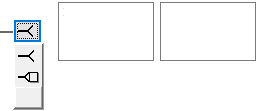
- Symbols
-
The Symbols buttons (A) specify the weld symbol type, as well as insert frequently used symbols such as number, diameter, plus-minus, and degree.
- Values
-
The Values buttons (B) extract weld data, such as base thickness, bead length, number of weld beads, and pitch.
 Symbols and Values
-
Opens the Select Symbols and Values dialog box for you to select other symbols and model-derived values without having to type the property text codes yourself.
- Field/Site Symbol
-
Specifies a flag points right symbol, a flag points left symbol, or none.
- All Around Symbol
-
Specifies the all around symbol or a solid line.
- Terminator Symbol
-
Specifies the same side symbol, the other side symbol, or a full arrow head.
- Reset
-
Clears all of the text from the weld symbol boxes, and resets the lines and arrows to the default selection.
- Permanent joint
-
Specifies how two materials are joined together. You can select the Permanent joint check box and then select the type of permanent joint symbol to embed in the leader line.
Example:
Fillet weld options
- Type
-
Specifies the type of fillet weld you want to construct. The type setting influences the size and shape of the fillet weld. You can specify that the fillet weld has equal or unequal setbacks, or that its size is determined by the bisector thickness.
- Dimension style
-
Sets the dimension style used for the fillet weld symbol. This setting determines how the fillet weld symbol is displayed in the Draft document.
- Symbol location
-
Specifies the location of the fillet weld symbol with respect to the reference line. You can specify whether the fillet weld symbol is displayed above, below, or on both sides of the reference line. You also can set the Override option if you want to set the weld system properties manually.
- Base Thickness
-
Defines the thickness of the base of the fillet weld. The base thickness of the fillet weld is aligned with the faces you select during the Select Base step. You also can set this option on the command bar when the Select Base step is active.
- Target
-
Defines the thickness of the target of the fillet weld. The target thickness of the fillet weld is aligned with the faces you select during the Select Target step. You also can set this option on the command bar when the Select Target step is active.
- Note prefix
-
Adds a prefix to the Notes box that is displayed in front of the weld symbol. For example, when you define a base and target thickness for the fillet weld, these values are automatically entered in the Notes box. When you add a prefix to the Notes box, the prefix characters display in front of the base and target values.
- Save As Defaults
-
Saves the current fillet weld options settings as the default. Saved defaults are used the next time you use this command. If you do not save the current settings as defaults, the previous default settings are used.
© 2021 UDS