Create a section view
Create a section view
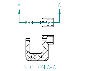
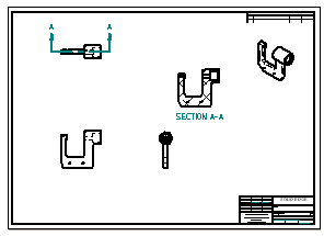
In the next few steps, create a section view, as shown above.
To create section views, first define a cutting plane on an existing drawing view using the Cutting Plane command.
Then use the Section command to select the cutting plane and place the section view.
Launch the Create a section view activity.
Select the drawing view for the cutting plane
-
Choose Home tab→Drawing Views group→Cutting Plane command
 .
. -
On the drawing sheet, click the drawing view shown below.
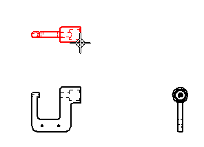
The command ribbon changes to display commands for drawing 2D elements.
The Line command is active.
Use the Zoom Area command
-
At the bottom-right side of the QY CAD application window, click Zoom Area
 .
. -
Click above and to the left of the drawing view, and then click below and to the right to zoom in around the drawing view.
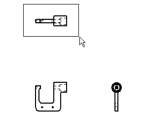
-
After resizing the view area, right-click to exit the Zoom Area command.
Zoom in to draw the cutting plane line.
Draw the cutting plane
-
Ensure that the Home tab→Draw group→Line command
 is running.
 -
Position the cursor over the midpoint of the edge shown in the illustration below, but do not click.

-
When the midpoint relationship indicator displays, move the cursor to the right as shown below.
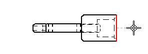
Notice that a dashed line displays between the highlighted edge and the cursor. This indicates that the start point of the line is aligned to the midpoint of the edge.
-
Click to place the start point of the line.
-
Move the cursor to the left as shown below, and when the horizontal relationship indicator displays, click to place the end point of the line.
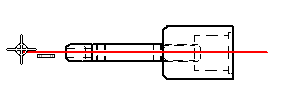
-
Right-click to restart the Line command.
-
Choose Home tab→Close Cutting Plane
 .
.The cutting plane options are hidden.
The cutting plane line should display similar to the illustration below.
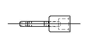
Specify the cutting plane direction
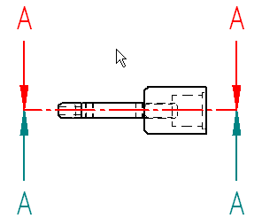
-
Move the cursor above and below the cutting plane line, and notice that the view direction arrows flip as the cursor crosses the cutting plane line.
-
Position the cursor above the cutting plane line, as shown in the illustration above, and then click to define the cutting plane direction.
The cutting plane should display as shown below. Depending on the template used to create the draft file, the cutting plane direction arrows might display with a different symbol.
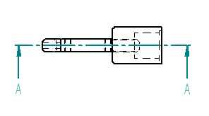
Fit the view
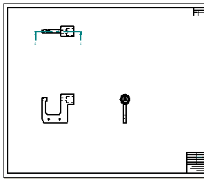
-
On the status bar at the bottom of the application window, choose Fit
 to fit the drawing sheet to the application window.
Create a section view
-
Choose Home tab→Drawing Views group→Section
 .
. -
Click the cutting plane line created previously, as shown below.
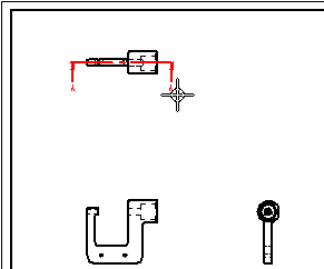
-
Position the cursor as shown below, and then click to place the section view.
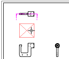
Move the section view
-
Press Esc to start the Select command
 .
. -
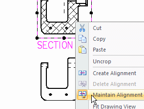
Position the cursor over the section view, and then right-click to display the shortcut menu.
-
On the shortcut menu, click Maintain Alignment to clear the Maintain Alignment option, as shown above.
-
Drag the cursor to move the section view to the location shown below.
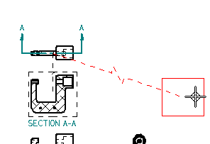
Notice that a dashed line connects the selected section view to its source view.
This indicator makes it easy to determine the source view for the section view later.
-
Click in empty space to clear the selection of the section view.
When creating a section view, by default it aligns with its source view. To move the section view independently of its source view, clear the Maintain Alignment option first.
Save the file
-
On the Quick Access toolbar, choose Save
 .
.
© 2021 UDS