Create an exploded assembly view
Create an exploded view of the assembly
![]()
In the next few steps, create an exploded view of the assembly.
Launch the Create an exploded assembly view activity.
Start the Explode-Render-Animate application
![]()
-
Choose Tools tab→Environs group→ERA
 .
.The system displays menus and commands specifically tailored for creating exploded views, renderings, and animations of an assembly in the QY CAD Explode-Render-Animate (ERA) application.
-
If the Explode PathFinder pane obscures the view, close it. It is not needed for this tutorial.
Start the Automatic Explode command
![]()
The Auto-Explode command (also referred to as the Automatic Explode command) explodes assemblies based on the relationships applied between parts. In assemblies where the components are positioned using mate or axial align relationships, the Automatic Explode command quickly gives excellent results.
-
Choose Home tab→Explode group→Auto Explode
 .
. -
On the Automatic Explode command bar, ensure that the Select option is set to Top-Level Assembly.

-
On the command bar, click Accept
 .
.
Use the Automatic Explode command to begin defining the exploded assembly view.
Set the Automatic Explode Options
When using the Automatic Explode command on an assembly that contains subassemblies, specify whether the parts in subassemblies are exploded or grouped together as a single unit.
For this assembly, explode the subassemblies also.
-
On the Automatic Explode command bar, click the Automatic Explode Options button
 .
. -
On the Automatic Explode Options dialog box, clear the Bind All Subassemblies option.
Clearing this option allows the parts in subassemblies to explode.
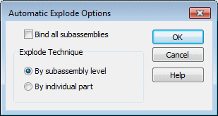
-
Also ensure the By subassembly level option is selected.
-
Click OK.
Create the automatic explosion
![]()
-
On the Auto Explode command bar, click Explode.
The system processes, and then displays the exploded view.
-
On the Auto Explode command bar, click Finish.
Notice that the display is good, but it would be easier to visualize the exploded view on a drawing sheet if the exploded view was more compact.
In the following steps, use other commands to adjust the positions of the parts within the exploded view.
Prepare to move the parts
![]()
In the next few steps, use the Move Part command to move the parts shown to reduce the space requirements of the exploded view.
First move the set of parts downward along the Z axis, then move the set of parts to the left along the X axis.
Start the Drag Component command
-
Choose Home tab→Modify group→Drag Component
 .
. -
Examine the options on the Drag Component command bar.

Use the Drag Component command bar to specify whether to move only the selected part, or the selected part and all its dependent parts.
You also specify whether to move the parts linearly, rotate the parts, or move the parts about a plane.
Note:This command cannot be used to move a part past an adjacent part.
Use the Drag Component command to move one or more parts in an exploded view along a specified axis.
Select the parts to move
![]()
-
On the Drag Component command bar, ensure the Move Dependent Parts option
 is set.
 -
On the Drag Component command bar, ensure the Move option
 is set.
 -
Position the cursor over the Barrel1.par part, as shown above, and then select it.
Notice that all the parts to the right of the barrel are also selected.
-
On the Drag Component command bar, click Accept
 , or right-click.
As shown below, notice that a triad displays, with the X axis highlighted. When moving parts, the X axis is automatically aligned with the original explode vector for the selected parts.
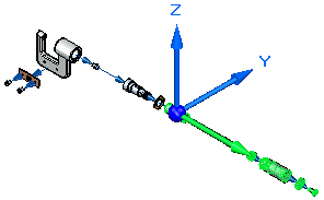
For this operation, move the parts as shown above.
Move the parts along the Z axis
![]()
-
Position the cursor over the Z axis, then select the Z axis.
-
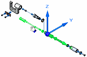
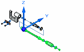
Press and hold the left mouse button down, then drag the cursor down as shown below, then release the mouse button to move the parts.
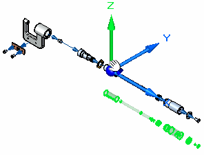
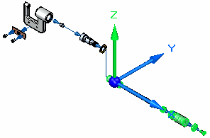
Move the parts along the X axis
![]()
-
Position the cursor over the X axis, and then select the X axis.
-
Press and hold the left mouse button, then drag the cursor to the left as shown below, and release the mouse button to move the parts.
-
Right-click to clear the selection and restart the command.
Fit the view
![]()
-
Choose Fit
 to fit the contents of the view to the graphics window.
Save the display configuration
-
Choose Home tab→Configurations group→Display Configurations.

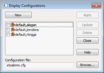
The Display Configurations dialog box displays.
-
On the Display Configurations dialog box, click New, type EXPLODE1 as the name of the display configuration, and then click OK.
-
Click the Close button to dismiss the dialog box.
To use this exploded view in an assembly animation or in an assembly drawing, save the display configuration.
Unexplode the assembly display
![]()
-
Choose Home tab→Modify group→Unexplode
 .
.A dialog box displays warning that the exploded view will be deleted if no display configuration of the exploded view is saved.
-
On the dialog box, click Yes.
-
Choose Fit
 to fit the contents of the view to the graphics window.
Because an exploded view configuration was saved, use the Unexplode command to return the assembly display to the assembled condition. This command is also useful when creating several exploded view configurations.
Close the Explode-Render-Animate application
![]()
-
Choose Home tab→Close group→Close ERA
 to return to the main Assembly environment.
 -
On the Quick Access toolbar, choose Save
 .
.
Exploded view creation complete
![]()
The assembly modeling portion of this tutorial is complete.
Although there are many more options available in the Assembly environment, you have learned the basic concepts required to build and explode assemblies in QY CAD.
© 2021 UDS