Edit a component in the assembly
Edit the frame in the context of the assembly
![]()
In the next few steps, edit the anvil end of the frame in the context of the assembly, as shown.
Also learn how to show and hide parts using PathFinder.
Launch the Edit a component in the assembly activity.
Hide the spindle part
-
The Select command should be active. If not, press Esc.

-
In PathFinder, click the + symbol to expand the SpindleSub1.asm entry to display the list of parts in the subassembly.
-
Position the cursor over the check box adjacent to the Spindle1.par entry, and then click to clear the check box.
In the graphics window, notice that the spindle part is hidden.
Change the Selection priority options
-
Choose Home tab→Select group→Select Options (the arrow pointing down, below the Select button)→Face Priority option.
The Face Priority option makes it possible to select faces before parts. This is a useful option when editing a model by moving faces with the steering wheel.
Select a set of faces by dragging a fence
![]()
-
Position the cursor at the approximate location shown in the top illustration.
-
Click+drag the cursor to the approximate location as shown below.
The steering wheel, Move command bar, and the Design Intent panel display.
Observe the steering wheel, command bar, and Design Intent
Notice the new tools that display when selecting the face:
-
The steering wheel displays at the location on which the face was selected.
-
The Move command bar displays.
-
The Design Intent panel displays.
Learn more about these tools in the next few steps.
Design Intent overview
- Design Intent panel
-
The Design Intent panel automatically displays when moving faces, defining 3D relationships, or editing dimensions in a synchronous model.
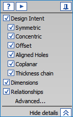
- Advanced Design Intent panel
-
The active options in the Design Intent panel and Advanced Design Intent panel are used to control how much of the design intent that has been built into the model to preserve or ignore when you move a face using the steering wheel.

Depending on the current computer configuration, the Design Intent relationships settings may be different than the illustration.
-
Click Advanced.
-
In the Advanced Design Intent panel, click the Restore
 .
.
Design Intent relationship settings should now match the illustration.
Select the vertical axis on the steering wheel
-
Position the cursor over the vertical axis on the steering wheel, and when it highlights, click to select it, as shown above.
-
Move the cursor above the model vertically.
-
Notice the following:
-
The dynamic input box displays near the cursor in order to enter a precise value.
-
The right end of the frame part moves vertically along with the selected faces.
-
The unselected parts in the assembly also move vertically.
-
Several Design Intent Advanced options now glow green, as shown below.
-
Finish moving the faces
-
Move the cursor above the selected face set until the value in the dynamic input box is about 6 mm.
-
In the dynamic input box, type 6, then press Enter.
-
Press Esc to deselect the faces.
The assembly updates as shown below. Notice that the selected faces on the frame, the anvil part, and the unselected parts all update their positions.
Display and save the spindle part
-
In PathFinder, position the cursor over the check box adjacent to the Spindle1.par entry, then click to redisplay the spindle part.
In the graphics window, notice that the spindle part displays again.
-
On the Quick Access toolbar, choose Save
 .
.
You are finished modifying the assembly by moving faces within a part in the assembly.
© 2021 UDS