Tutorial: Simulate torque on a mower hub
Use linear static analysis to simulate torque stresses on the shaft of a lawn mower hub, at a steady-state condition. Use the Torque command to apply a turning force to one or more faces about an axis of rotation.
The study parameters used in this tutorial are:
-
Structural Study type=Linear Static
-
Load type=Torque
-
Constraint type=Fixed
-
Mesh type=Tetrahedral
-
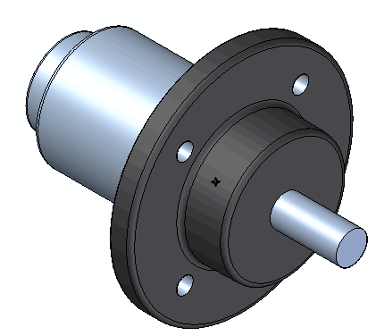
Open the file named FE_mower_hub.par.
Simulation models are delivered in the \Program Files\UDS\QY CAD 2022\Training\Simulation folder.
-
Create the study.
Note:The material is already defined: Stainless steel.
-
Select Simulation tab→Study group→New Study.

-
In the Create Study dialog box, choose the Linear Static study type and Tetrahedral mesh type, and then click OK.
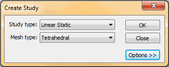
The study is created and is active, as indicated on the ribbon in the Study group on the Simulation tab.

-
-
Define the torque load.
-
Select Simulation tab→Structural Loads group→Torque
 .
. -
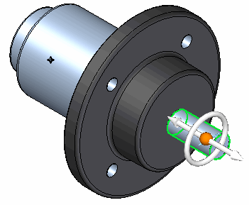
Select the hub shaft.
-
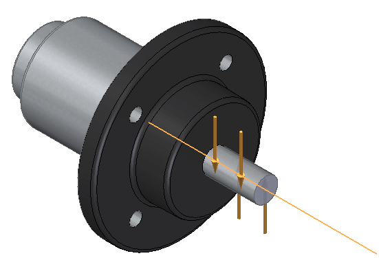
Type 100 N-m for the torque value. Press Enter.

-
Left-click in space to finish.
-
-
Define a fixed constraint:
-
Select Simulation tab→Constraints group→Fixed.

-
Select the end face of the hub shaft.
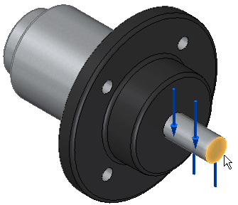
-
Right-click to apply the constraint.
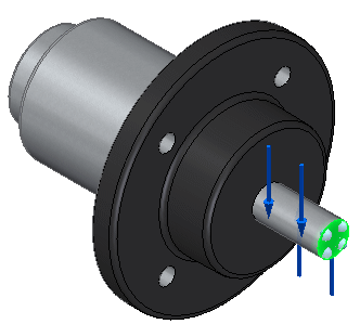
-
-
Mesh and solve the study:
-
Turn off constraints and loads in the Simulation pane.
-
Select the Mesh command. Choose Mesh & Solve.
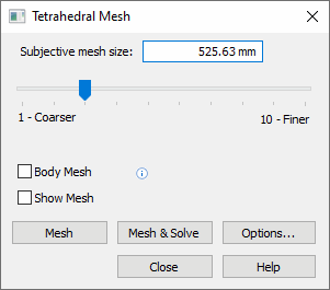
The part is meshed and solved. The units for stress are expressed in megapascals (MegaPa).
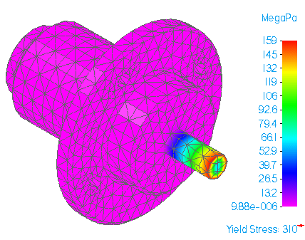
-
-
Close this file.
© 2021 UDS