Use motion loads in linear static studies
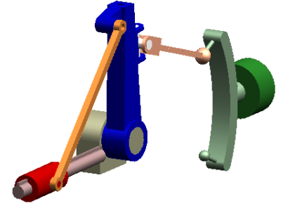
Follow this process to create moving parts directly from your assembly components, and motion joints directly from assembly constraints. You can then add motion generators and apply loads. After you run a motion simulation, you can use the motion results to animate your moving assembly, and to check for interference as the assembly moves through its full range of simulated motion.
To use QY CAD Motion as input to QY CAD Simulation, you transfer the resulting motion loads at any motion time-step to the corresponding part(s) in a previously created FEA study.
Two versions of motion simulation are available—basic motion and dynamic motion—and your license type determines which commands are available for use on the command ribbon in the Motion environment. Basic motion is included in QY CAD at no charge. Dynamic motion simulation is included with a QY CAD Premium license or a QY CAD Simulation license.
This workflow introduces you to the motion simulation interface terminology and the order in which you define the motion study and the FEA study, so that they can work together. To open the CHM-format help file and tutorials, see Learn to use QY CAD Motion.
Define a motion mechanism
-
Open your assembly model in QY CAD.
-
To use the motion results with QY CAD Simulation—Verify that a structural study exists in the document, or select the Simulation tab→Study group→New Study command to create a new study now. (For example, select the Linear Static study type.) The study does not have to be solved, nor does it need to contain loads and constraints. You just need to create the study container and select the study geometry.
Tip:The assembly components included in the FEA study geometry must also be included in the motion study.
Turn off the display of any assembly connectors, loads, or constraints in the FEA study to reduce clutter in the motion study.
-
Review your product concept. Identify the components of interest, how they are connected, and what drives the movement of the components. Determine which characteristics of the product you want to understand. You can use PathFinder to temporarily hide the components that you do not want to include in the motion simulation.
-
Open the Motion environment—Choose Tools tab→Environs group→Motion
 .
.-
The Motion tab is added to Assembly PathFinder.
-
A Motion Model container is shown in the pane below. This is the Motion browser, which you use to create, edit, and delete objects in the motion study.

-
-
Select the parts that participate in the mechanism using any of the following methods. Parts represent a rigid body whose motion is to be simulated. You designate a part as a moving part or as a non-moving (ground) part. A moving part has six degrees of freedom, while a ground part has none. A ground part has a symbol attached to show that it has been grounded.
- Automatically
-
The first time you open an assembly in the Motion environment, a dialog box lists all the parts in the assembly, and prompts you to indicate if you want to Automatically add new parts as grounded or moving parts?
On subsequent file-open, or if you select the New Mechanism command, you can use the Motion-Add New Parts dialog box to achieve the same results.
Tip:If you decline the automatic method, all of the parts in the assembly are added to the Assembly Components node in the Motion browser. You can then select individual parts and drag them into the Moving Parts or Ground Parts nodes.
- Manually
-
Select the Home tab→Mechanism group→Builder command, click the Parts tab, and then selectively assign parts as moving parts or grounded parts by dragging them to the appropriate list within the Motion Builder.
Tip:The Motion Builder is the primary interface in motion simulation. It is a tabbed dialog box and a wizard that leads you through the process of creating a motion model from your assembly, performing the motion simulation, and viewing the simulation results. To open the associated help topic:
-
Click
 .
. -
Click a control in the wizard.
-
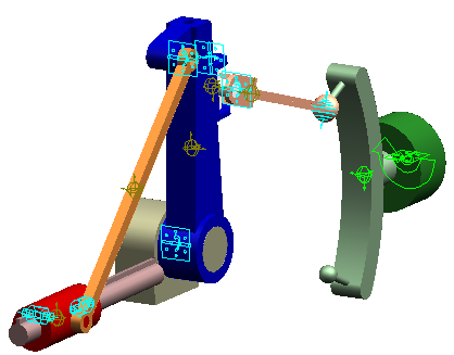
With the automatic or the manual method, relationships (for example, axial, planar, symmetric) are detected and are displayed in a message box. These are used to generate motion constraints automatically. In the Motion browser, expand the Constraints→Joints node to see them in one list. Continue expanding the nodes to identify the constraint ID and to see the parts where they are applied.

-
(Optional) In the previous step, constraints were identified in the assembly and created automatically in the motion model. To add more constraints in your mechanical system to connect the parts, you can:
-
Right-click the Constraints node in the Motion browser, select the type of constraint to add, and then select the components on the QY CAD model that you want to constrain.
-
Use the Joints tab in the Motion Builder.
Note:Any elements that move as a unit are defined as a rigid body. Constraints define how rigid bodies are attached and how they move relative to each other. A joint constrains the relative movement of a pair of rigid bodies by physically connecting them.
Joints remove degrees of freedom from the parts to which they are attached. You can also rigidly connect a part to another part using a fixed joint.
-
-
Apply motion to the constraints in your mechanism—You can define a motion generator directly on a part using shortcut commands on the Constraints node in the Motion browser. You also can use the Motion tab in the Motion Builder. You can provide input to a motion using a built-in function or by creating your own function.
Example:A motion can input either rotational or translational motion as a function of time. The function, TIME * 360d, defines a motion driver that rotates one body one complete revolution (360 degrees) with respect to another body per unit of time.
-
(For dynamic motion) Add motion loads using shortcut commands on the Forces node in the Motion browser. Loads applied in motion studies are like structural loads in FEA studies: external forces and torques that act on your mechanism.
-
You can define gravitational force, resistance force (springs, dampers, bushings), or other loads acting on your mechanism, including applied force, applied moments, action/reaction, and impact force.
-
Each force requires a force direction and a force magnitude. To define a force magnitude, you can enter values, use a predefined function (step, harmonic, spline), or create an expression function using the Function Builder.
Note:Forces define loads and compliances on parts. Forces do not absolutely prohibit or prescribe motion. Therefore, they do not add or remove degrees of freedom from your model. Forces may resist motion or they may induce motion.
-
-
(For QY CAD Simulation) Define the load-bearing faces on which the motion forces and moments can be distributed.
-
In the Motion browser, right-click a selected force and choose Properties.
-
In the Edit dialog box, use the FEA tab to assign the load-bearing faces.
Note:Motion simulation calculates the forces and moments on each constraint by using part mass, center of mass location, inertia tensors, and constraint locations as the basis for its solutions. Think of it as solving a free-body diagram (or skeleton structure), showing only these elements. Unless using 3D contacts, it is not concerned with the physical geometry. As a result, it resolves these forces and moments at single-point locations (the location of the constraints) rather than on geometric surfaces. For QY CAD Simulation to recognize that the resulting forces and moments are distributed among specific faces, you must define the faces that will bear the loads.
-
Run a motion simulation
-
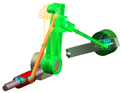
Run the motion simulation—You can do this using the Simulation tab in the Motion Builder, the Simulation command on the command ribbon, or the shortcut commands from the Mechanism node in the Motion browser.
The solver calculates the displacement, velocity, acceleration, and reaction forces acting on each moving part in the mechanism.
-
Use the Motion Builder to review the motion simulation results.
-
On the Animation tab—You can review the motion of the mechanism frame by frame or in set increments. You also can display a specific segment of the motion.
-
On the Interference tab—Check for and show interfering parts.
-
Transfer the calculated motion loads to your FEA study
You can use the numeric output of the motion simulation to better understand the various characteristics of your mechanism. For example, QY CAD Motion reports the loads for each joint and motion. Joint loads can be used as load cases for the structural analysis of any component in your mechanism.
-
On the Motion command ribbon, select the Home tab→Replay group→Player command to reopen the Motion player toolbar to review the motion step-by-step.
-
When you find a step that you want to add to your FEA study, scroll down to the bottom of the Motion browser, expand the + sign next to the study name (such as Static Study 1), right-click the part name, and choose Add Loads.
When you add loads to a QY CAD Simulation study that already has loads defined in it, you are prompted to choose one of the following options:
-
Delete Loads—Deletes all existing loads in the FEA study before adding the new loads.
-
Add Loads—Adds the new loads to the existing loads.
-
-
Close the Motion environment and click the Simulation tab in PathFinder. In the Simulation study navigator pane, right-click the linear static study name, Static Study 1, and choose Solve.
-
To add motion loads from another time-step in the motion study, return to the Motion environment. When prompted to delete the motion results, click No. Repeat the previous steps in this section.
To continue, the motion simulation results must be available in the document.
The stress analysis results do not change the motion study results.
© 2021 UDS