Create a section view using associative planes
-
Choose the PMI tab→Model Views group→Section by Plane command
 .
.The command defaults to the non-associative cut plane creation method.
-
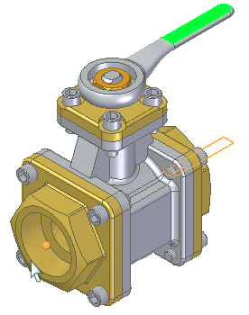
On the command bar, click the Select Parts Step
 . On the Cut List, click Cut only unselected parts. Select the parts shown then click Accept.
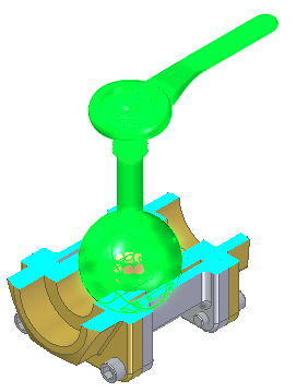
-
Click the Cutting Plane Step
 , and then click the Associative Plane button
  .Note:
The command bar changes to display the plane type creation list.
-
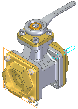
On the command bar, click Parallel Plane on the Plane Type list. Select the plane shown.
-
Position the cut plane at the center point shown. Click when the keypoint displays.
Click Accept.

-
Create another parallel cut plane. On the command bar, click the Cutting Plane Step and then click the Add Cutting Plane button
 .
. -
Select the plane shown.
-
Position the plane at the top flange edge midpoint shown and then click.
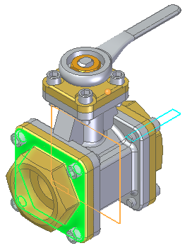
Click Accept.
Click Finish.
-
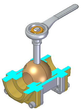
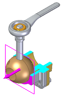
Change section view to a bounded display. On the command bar, click the Bounded button
 then click Accept.
Click Finish.
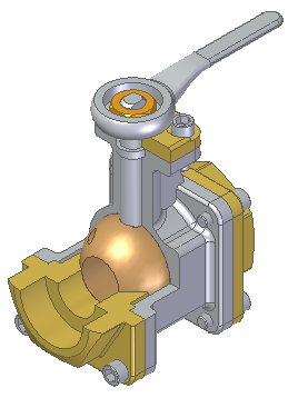
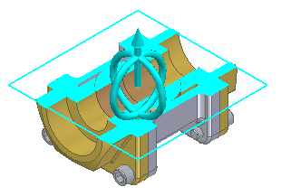
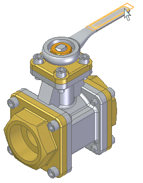
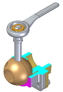
Create a section view of the assembly shown. Do not cut the handle, nut, shaft, and ball valve.
© 2021 UDS