Reference plane enhancements
Reference plane unification enhancements between part and assembly include:
-
The Tangent Plane command is now available in the assembly environment. Now the list of commands used to create reference planes is the same for both part and assembly.
-
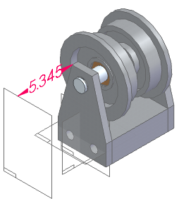
In assembly, placing a reference plane now places a dimension so you can use the Edit Definition command to edit the dimension without going into Variable Table.
-
The plane names in assembly PathFinder are now the same as they are in part. The name is a generic name, rather than a name based on the plane type. Previously, in assembly PathFinder the plane name reflected the plane type. For example, suppose you create a parallel reference plane in assembly. In PathFinder, the name for that reference plane would be Parallel x.
Note:The names of existing assembly reference planes do not change.
-
The reference plane icons for assembly are now used in PathFinder in both part and assembly to indicate the reference plane type.
Note:Synchronous reference planes will use the basic reference plane icon.
-
The P hot key is now available when creating a parallel or coincident plane in assembly. Use the P hot key to select a base reference plane to define the x-axis.
-
A new Resize Plane command
 on the part reference plane shortcut menu in part PathFinder changes the size of the reference planes.
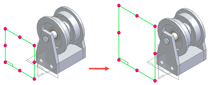
-
Editing reference planes is now consistent between part and assembly. The Edit Definition command and Dynamic Edit command are available when editing reference planes in part or assembly.
-
The reference plane edit handle now displays relative to the selected plane for both part and assembly.
-
Updates have been made to the commands found in the reference plane menus in ordered part, synchronous part, and assembly.
-
The reference plane collector from the part reference plane Edit command has been added to the assembly reference plane Edit command so you can now change the assembly reference plane type.
-
The reference plane icons in drawing views have been updated to be consistent with the icons for part and assembly.
-
Reference planes placed in assembly now use driving dimensions to position the reference plane, as is done in part. Previously, a variable value drove the position of the reference plane in assembly.
-
The icon used in drawing view properties now use the base reference plane icon used in part and assembly.
-
Changes have been made to the display of offset values for the Angled Plane, Parallel Plane, and Tangent Plane commands.
-
The entry in the relationship tree now indicates that a keypoint is used to define the position of the reference plane. Previously, the entry displayed the value for the reference plane position.
-
Clicking the entry in the relationship tree highlights the keypoint that was used to define the position.
-
The value of this entry is no longer displayed.
-
The box used to change the value is no longer displayed.
-
| Reference user profile information in a callout |
© 2021 UDS