Convert a solid to a mesh body
Convert to Mesh Body command
The Convert to Mesh Body command is associated with mesh modeling.
The Convert to Mesh Body command  is available from the shortcut menu that is displayed when you right-click a selected Design Body in the Design Bodies container in PathFinder.
This command converts the selected solid design body to a mesh. All the features previously associated with the design body are merged into a single mesh body feature, which is added to the Features container of PathFinder.
Use the options and controls on the Mesh Options dialog box to control how a model document is translated to a mesh format.
After conversion, the mesh body cannot be converted back to a solid body (b-rep) after you make any changes to the mesh. In an Ordered model, mesh features can be deleted at any time.
Mesh body faces
The mesh geometry is tagged with analytic geometric information. When the underlying geometry of a mesh is known, it is automatically “tagged” with geometric information such that it can be used more like a classic b-rep model.
Applications:
-
Geometry created with Mesh Modeling or Convert To Mesh.
-
Some imported mesh models that have been identified using Reverse Engineering Automatic or Manual.
-
Steering wheel behaves much more similarly to Classic modeling.
-
Axes and planes can be used in Part and Assembly.
-
Eligible faces and edges behave like b-rep geometry.
Mesh body display
The resulting mesh can be better observed by changing from the default Shaded with Visible Edges view (1) to a Wireframe view (2) as shown here:
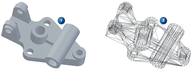
To obtain the wireframe view of the mesh, select the View tab→Style group→View Overrides command to open the View Overrides dialog box. From the Render mode: list, select the Wireframe option.
© 2021 UDS