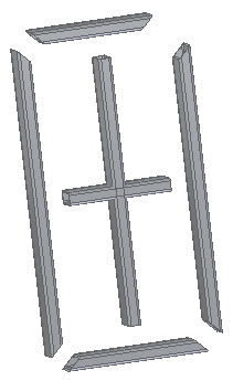
Create frames with weld gaps
In this procedure, the weld gap values are exaggerated for display purposes.
-
Choose the Frame command
 .
. -
On the Frame Options dialog box, click the Set weld gap value option. Type 35 in the value box.
-
Click Apply, and then click OK.
-
Select the path elements, and then right-click.

Click Finish.
-
Turn off the sketch element display.
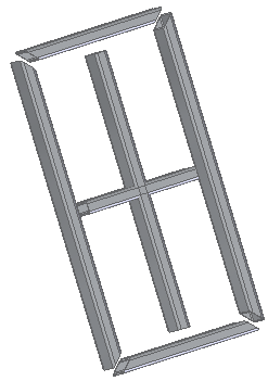
Create frames and apply a weld gap to all members.
Set weld gap for all frames
-
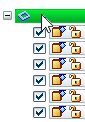
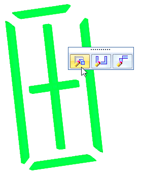
In Assembly PathFinder, select the frames collector shown.
-
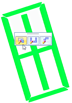
Click the Edit Definition button.
-
On the Frame command bar, click the Frame Options button.
-
Type 70 in the Set weld gap value box. Click Apply, and then click OK.
Change the weld gap value globally.
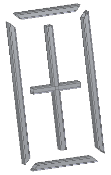
Set weld gap for single frame
-
Select a single frame.
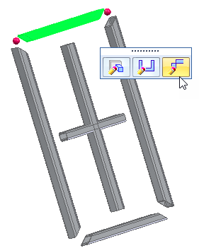 Note:
Note:If you click Edit End Conditions at this point, both ends (red dots) are edited.
-
To edit a single end, click the end shown.
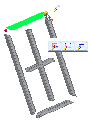
-
On the Frame command bar, click the Weld Gaps option and type 150.

Click Finish.
Change the weld gap value at one end of a single frame.
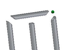
Clear overrides
-
In Assembly PathFinder, select the frames collector shown.
-
Click the Edit Definition button.
-
On the Frame command bar, click the Frame Options button.
-
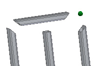
On the Frame Options dialog box, click Clear Overrides.
Notice the message:
 Cleared corner treatment overrides for 1 end(s).
Click OK, and then click Finish.
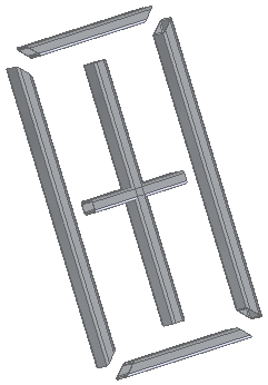
Observe the result when Clear Overrides is selected.
© 2021 UDS