Cylinder command in Subdivision Modeling
In the Subdivision Modeling environment, the Home tab→Shapes group→Cylinder command  creates a cylindrical shape with smooth or hard edges as the basis for your subdivision feature.
Specifying creation methods
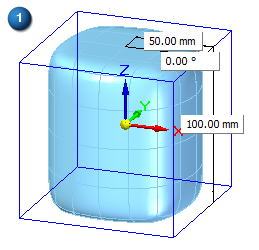
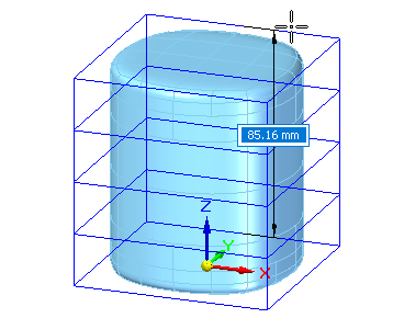
The default creation method is At Origin, with the Smooth edges option  selected, as shown in the following example.
You can change the default initial dimensions on the shape and the settings on the command bar.
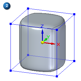
Right-click to accept and finish the basic shape.
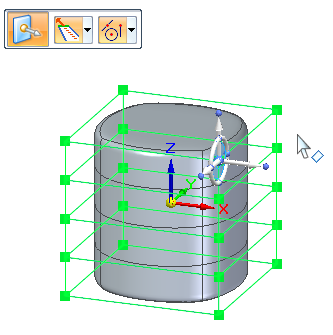
The steering wheel is displayed at the origin of the file, so you can move or rotate the cage edge or face while still in placement mode. The more cage segments you create in the base shape, the more faces you have to manipulate.
You can change the creation method to By 3 Points using the Selection Type list on the command bar. You define the center point (P1) and side point (P2) on the top face, and then the extent or height of the cylinder.
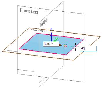
With this method, you also can use the Symmetric option  on the Cylinder command bar.
Specifying initial segments (faces)
For all placement options, you can use the command bar to set the number of cage segments on the side and the base. Cage segments define the number of edges that you can manipulate, with more faces providing more detail.
From left to right:
Side segments=3, Base segments=5
Side segments=1, Base segments=8
Side segments=2, Base segments=12
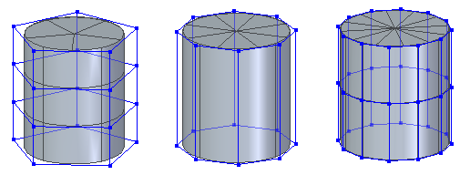
You can control the size and color of vertices and edges using the Home tab→Style group→Cage Style command  .
.
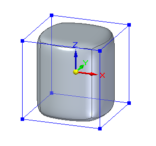
Specifying smooth or hard edges in the initial shape
The default cylinder-like shape is displayed with smooth edges.
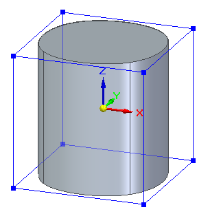
To create a shape with hard edges, turn off the Smooth option  on the command bar. The resulting shape is a traditional cylinder primitive.
© 2021 UDS