Constructing swept features
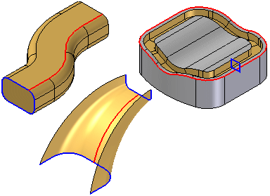
You can use the Swept Protrusion, Swept Cutout, and Swept Surface commands to create swept features.

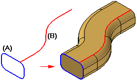
Swept features are constructed by extruding one or more cross sections (A) along one or more path curves (B).

You can define the paths and cross sections by:
-
Drawing a profile
-
Selecting elements from an existing sketch
-
Selecting edges on the model or a construction body
-
Selecting derived elements, such as intersection curves and derived curves.
Clamp conditions
You can control clamp conditions, the shape of the swept feature where the swept features meet between multiple cross sections, with the Clamp Control Handle.
The handle has two options:
| No Clamp | Specifies that no constraining condition is enforced on the cross section. |
|
| Clamp to Section | Specifies that the cross section is maintained for a length controlled by its magnitude handle. |
|
© 2021 UDS


