Define the extent of a revolved feature
-
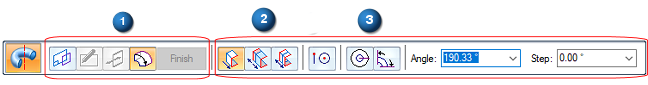
Verify the Extent Step (1) is active on the command bar.
-
Click an extent distance option:
-
One-sided Extent
-
Non-symmetric Extent
-
Symmetric Extent
-
-
Click an extent direction option:
-
Revolve 360 Degrees

-
Finite Extent

-
-
Use the dynamic arrows and the options displayed on the command bar to finish defining the feature extent. You can change the extent options at any time as you construct the feature.
To define an extrusion or cutout in the ordered environment, do the following:
When you are constructing or editing a part in the context of an assembly (you have in-place activated the part), you can use assembly reference planes to define the feature extent. This allows you to edit the feature extent from within the assembly, by editing the reference plane's offset value. Press and hold the Shift key while clicking the assembly reference plane.
| Construct a revolved feature with an existing centerline axis |
© 2021 UDS