Activity: Add draft to model faces
Add draft to model faces
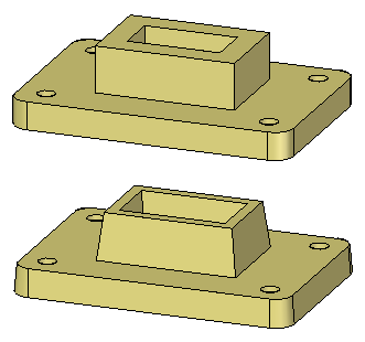
This activity demonstrates the process of drafting faces of a model.
Learn how to draft faces and how to edit existing draft features.
Click here to download the activity file.
Launch the Activity: Add draft to model faces.
Open the part file
-
Open the part file draft.par.
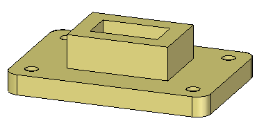
Add 5° draft to the chain of vertical faces on the base plate, outside faces on the boss and faces on the cutout.
Add draft to the base plate
-
On the Home tab→Solids group, choose the Draft command
 .
. -
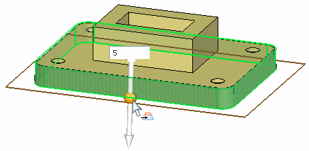
Select the bottom face of the base plate as the draft plane. The draft angle pivots at the draft plane.
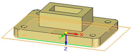
-
Select the chain of faces as shown.
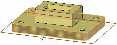
-
Click the origin of the direction handle to define the direction inward. In the dynamic edit box, type 5 for the draft angle and then press Enter.
Add draft to the boss
-
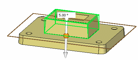
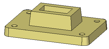
Add 5° draft to the four faces of the boss with direction inward. Use the top face of the base plate as the draft plane.
Add draft to the cutout faces
-
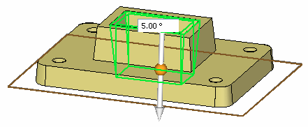
Add 5° draft to the four faces of the cutout with direction outward. Use the bottom face of the base plate as the draft plane.
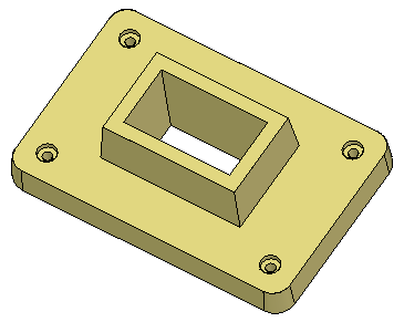
Edit a draft feature
-
Edit the draft feature on the boss. Select the feature with QuickPick or select the feature in PathFinder.
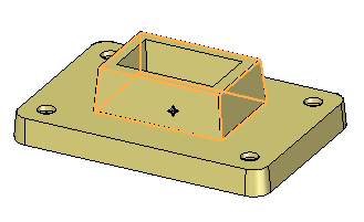
-
Click the 5° text to edit the draft parameters.
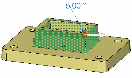
-
Change the draft angle to 7° and press Enter.
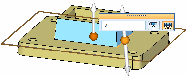
At this point the draft direction and draft plane can be edited also. Press Enter to apply the edit and then press Escape to end the command.
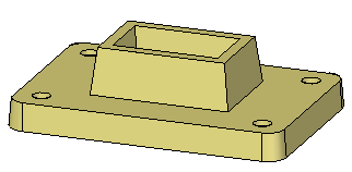
-
This completes the activity. Close the file and do not save.
Summary
In this activity you learned how to apply draft to faces on the model. A draft plane was selected to control the pivot point for the draft angle. If no face exists to use as a draft plane, you can create a plane and move it to the desired location. You also learned how to edit an existing draft feature.
-
Click the Close button in the upper-right corner of this activity window.
© 2021 UDS