Assemble command
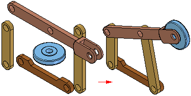
The Assemble command  positions parts in an assembly. You can use this command to position a single part, or you can use this command to position several parts relative to each other without fully constraining each part in an ordered sequence.
This type of workflow can make it easier to position a set of interrelated parts, such as when building a mechanism.
After dragging a set of parts into an assembly, you can use the Assemble command to apply relationships between one of the parts and one or more target parts. To position a different part, right-click.

To position a series of parts using the Assemble command, you first drag the set of parts into the assembly using the Parts Library tab.
If it is a new assembly, the first part is automatically grounded. When you drag and drop the second part into the assembly, the Assemble command bar is displayed, but you can continue to drag parts into the assembly without positioning them.
After the set of parts is placed in the assembly, you can use the Assemble command to position the parts.
When you click the Assemble command, the Assemble command bar is displayed. You can use the FlashFit option to apply a mate, planar align, or axial align relationship, or choose from the complete set of ordered relationships.
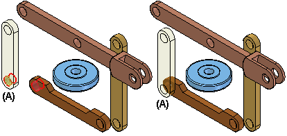
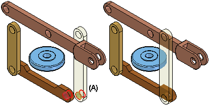
After you apply a relationship between two parts, the first part you select (A) remains selected so you can apply additional relationships to the part.

To position a different part, right-click. You can then select a different part (A) and apply the relationships you want.

The Assemble command is tightly integrated with the FlashFit positioning option. When you click the Assemble command, FlashFit is the default option. For more information on FlashFit, see the Assembly Relationships topic.
Assemble command behavior
Actions within the Assemble command:
-
FlashFit is the default assembly relationship creation mode and should be used.
-
After you select a part to position, it becomes transparent. After it is fully positioned, or another part is selected, it is no longer transparent.
-
If, in the middle of positioning a part, you decide to position another part, right-click to release the current part. It is no longer transparent. The next part you select then becomes transparent.
-
If you work in wireframe, rather than shaded, you will not have the visual benefit of the selected part being transparent. For that reason, we suggest that you use Shaded with Visible Edges display mode while using the Assemble command.
-
After you select a part, you can drag it to a new position using the left mouse button. The selected part is the part to which you are applying relationships. Right-click to release the part.
-
To rotate a selected part that is unconstrained, use CTRL + click.
-
FlashFit determines whether to use a Mate or Planar Align relationship based on the closest orientation of the faces being matched. It is good practice to rotate the selected part into the approximate position before selecting the faces. After FlashFit, if the faces are 180° out of position, click the Flip button on the command bar.
-
Matching circular edges quickly positions a part, such as a fastener, in one operation. The axes are superimposed and the rotation is locked. You can unlock the rotation by editing the relationships in Assembly PathFinder. Refer to the section of this activity that addresses editing and error recovery.
© 2021 UDS